Articles
Tackling flow measurement challenges for hydrogen fuels
D. ANDERSON, TÜV SÜD National Engineering Laboratory, Glasgow, Scotland, UK
Hydrogen is recognized as playing a crucial role in global net-zero carbon targets, through its potential use in vehicles and in domestic heating. This is because H2 contains no carbon, so when used in a fuel cell or combustion engine its only product is water vapor. However, due to the low abundance of elemental H2 in the earth’s atmosphere, H2 must be first produced before it can be used as a fuel. This means that it is referred to as an energy carrier and, unlike hydrocarbons, is not an energy source.
When discussing the use of H2 in a low-carbon economy, green H2 is commonly referred to; this is H2 generated from the electrolysis of water, using renewable energy such as solar, wind or tidal. Generation of H2 from renewable sources provides a buffer that allows excess energy to be stored in periods of peak generation.
However, the most common method for H2 production is either through steam methane reforming (SMR) or autothermal reforming (ATR) of hydrocarbons, such as natural gas, primarily due to the lower cost relative to electrolysis. This process produces carbon dioxide as a byproduct; therefore, CO2-reducing technologies, such as carbon capture, utilization and storage (CCUS), are required to avoid CO2 being released to atmosphere. When a carbon-reduction technology such as CCUS is used alongside SMR or ATR, the H2 produced is commonly referred to as blue hydrogen.
Flow measurement challenges for hydrogen vehicles. The use of H2 as an alternative to refined oil products and natural gas for transport is receiving much attention. Like battery-powered electric vehicles (BEVs), the use of H2 fuel cell electric vehicles (FCEVs) will reduce local air pollution due to the absence of tailpipe emissions. Provided that either green or blue H2 is used, overall CO2 emissions will also be reduced. For BEVs, which use electricity from the electricity grid, the overall CO2 emissions will be reduced if the method of electricity generation emits less CO2 per charged vehicle than those which use hydrocarbons as a fuel.
Globally, BEVs are significantly larger in number than FCEVs, at present. The capital costs associated with building an H2 refueling station mean that they are less common than the relatively low-cost BEV charging points. However, FCEVs do have several advantages, such as a larger range of 400 km and above, compared to a range of around 250 km for BEVs. In addition, FCEVs can be refueled in a few minutes, whereas BEVs can take several hours to recharge their batteries.
One aspect that is commonly overlooked for FCEVs is the ability to effectively trade H2. For BEVs, this is relatively simple since the necessary standards are already in place to measure electricity usage. For the FCEV industry, the challenge of measuring H2 dispensed into the tank is not as simple, particularly when customers using these refueling stations will expect a similar level of measurement error to what is presently achieved in gasoline and diesel refueling—i.e. –1 % to +0.5 %.
The accuracy requirements for dispensers at H2 refueling stations are set out in the international recommendation OIML R139. A maximum permissible error (MPE) of ±1.5 % is stipulated for the flowmeter and ±2% for the complete measuring system at initial verification, which is challenging due to the operating conditions at H2 refueling stations. These are specified in the worldwide accepted standard SAE J2601. A schematic diagram of an H2 refueling station is shown in FIG. 1.
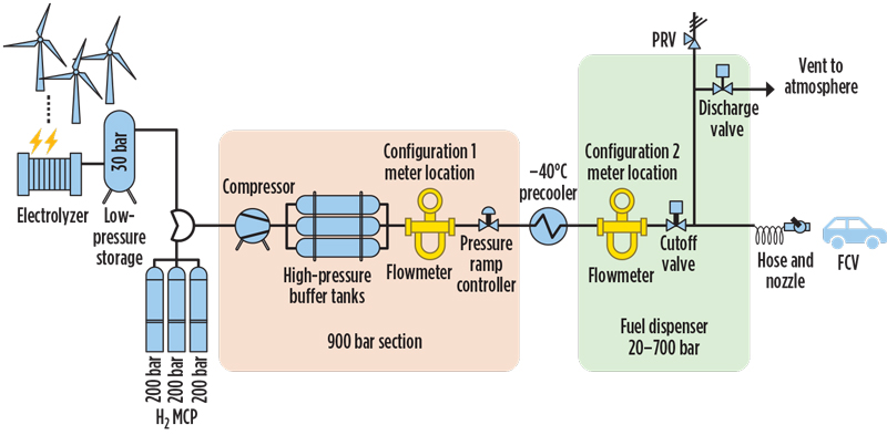
Fig. 1. Schematic diagram of an example of a hydrogen dispenser. Photo courtesy of TUV SUD Ltd.
The flowmeters used at refueling stations are Coriolis mass flowmeters, with the exact location of these dependent on the design of the refueling station. Two common locations are upstream of the precooler near the compressor, and in the dispenser unit downstream of the precooler; both locations are shown in FIG. 1. Coriolis mass flowmeters perform best when calibrated at temperatures and pressures close to field operating conditions, and ideally using the same fluid. However, vehicles are filled at up to 700 bar, and the temperature within the refueling station can reach up to 60°C from precooling at –40°C. At present, no independent flow calibration laboratories can operate with H2 at these conditions to enable the calibration of Coriolis mass flowmeters.
Some sources of flow measurement error are unrelated to the accuracy of the flowmeter. For example, for safety reasons, the dispenser hose must be vented after use. Since the hose is located downstream of the flowmeter, this represents a quantity of H2 that has been measured but not delivered to the customer. A correction must be applied for the vented H2; otherwise, it is an additional source of measurement error.
In addition, once the dispenser hose is vented, a large volume of pressurized H2 may still remain in the piping further upstream, particularly if the flowmeter is installed upstream of the precooler. This “dead volume” contains gas that has been measured by the flowmeter but not delivered to the receiving vehicle. If the current user fills their vehicle to a higher pressure than the previous user, there will be a positive error and the user will be over-charged, and vice versa. Once again, corrections must be applied to ensure that the user has been billed correctly.
To assess the magnitude of error at the dispenser, several field test standards have been developed, with the U.S. National Institute for Standards and Technology (NIST) being the first. Four more have been developed through the EMPIR Joint Research project (JRP), Metrology for Hydrogen Vehicles (MetroHyVe) and by several national metrology institutes and designated institutes: METAS, Justervesenet, CESAME-EXADEBIT and VSL. Korea Research Institute of Standard and Science (KRISS) has also developed a field test standard for use in South Korea. TÜV SÜD National Engineering Laboratory is planning to build two field test standards, one for dispensers filling light-duty vehicles and the other for heavy-duty road transport vehicles.
The MetroHyVe project partners, which include TÜV SÜD National Engineering Laboratory, have completed a test program to assess the potential sources of error from the flowmeter. Effects of pressure and temperature were investigated, along with the potential to use alternative fluids to calibrate the flowmeters prior to installation. Since Coriolis mass flowmeters are based on mass flow measurement, the use of alternative fluids, such as air, nitrogen and water, would allow calibrations to be undertaken at significantly lower pressures and ambient temperatures while still achieving the same mass flowrate.
Some positive results were seen in these trials; the flowmeters tested performed well over a range of constant temperatures and pressures representative of those found in a refueling station. Also, alternative fluids were shown to be suitable for the calibration of flowmeters, removing the need to calibrate using H2 in challenging operating conditions and reducing the cost of calibration. Another positive result was that pressures of up to 850 bar had an insignificant influence on flowmeter performance.
The JRP MetroHvVe II, launched in September 2020, aims to further develop a metrological traceable framework for testing H2 dispensing meters. One task of this project is to develop primary standards for heavy-duty H2 vehicles, which have a refill of approximately 30 kg–40 kg compared with 4 kg–6 kg for passenger vehicles. Additionally, the project will look at the development of secondary standards that are traceable to the primary standards developed in the initial MetroHyVe project for verification of H2 refueling stations.
As it is costly to build primary standards and time-consuming to undertake the verification process using them, secondary standards could help reduce the cost and time needed for verification. Also present in this project are non-flow activities such as the development of H2 fuel reference materials, guidance for the implementation of analyzers and sensors at H2 refueling stations, standardization of the sampling methodology at H2 refueling stations and the development of a harmonized protocol for fuel cell stack testing.
Flow measurement challenges for hydrogen-based heating. H2 is also being considered for use as an alternative to natural gas in domestic applications such as gas boilers, cookers and fires. This can either be in the form of H2 or blends of H2 with natural gas. H2 has the obvious advantage of producing only water vapor as a combustion product.
Provided that the hydrogen used is either green or blue H2, no CO2 will be released into the atmosphere. The use of H2 blended with natural gas does not have this advantage but will still result in a decrease in CO2 emissions compared to using only natural gas.
Despite the advantage of an H2-only fuel, the use of H2 and natural gas blends should not be dismissed. In the UK, the use of the blended gas has been investigated by the HyDeploy project, with results showing that up to 20 mol% H2 can be blended into natural gas and used without any modifications to the appliances. This may provide a suitable interim solution until appliances are modified for use with H2.
Regardless of whether H2 or blends of H2 with natural gas are used, the accuracy requirements set out for domestic gas flowmeters must be met to ensure the accurate billing of consumers. In Europe, the requirements for domestic gas meters are stipulated in the Measuring Instruments Directive (MID), which is European Directive 2004/22/EC. This directive was established to develop a single market for measuring instruments throughout the EU.
Flowmeters used for domestic gas metering must demonstrate conformance to the MID, which can be achieved in three different ways:
- Conforming with a harmonized standard for the measuring instrument that has been published in theOfficial Journal of the European Union
- Conforming with parts of normative documents that have been listed in theOfficial Journal of the European Union
- Conforming directly against the essential requirements described in the MID.
The most common domestic gas flowmeter used in the UK is the diaphragm-type meter. The device consists of a housing containing four chambers, two of which are enclosed by bellows that expand and contract as they are charged and exhausted, respectively. Flow into and out of the chambers is accomplished by means of slide valves. The volume of gas passed through the meter is obtained through a linkage arrangement, connecting the diaphragm to a mechanical readout system that records the number of displacements.
Diaphragm meters demonstrate conformity to the MID through the harmonized standard for diaphragm domestic gas meters: BS EN 1359:2017. This standard requires that diaphragm gas meters must conform to the Class 1.5 within the MID. In terms of flowmeter accuracy, this essentially means that the MPE is ±1.5% on initial testing, with allowances up to ±3% for the lower 10% of the flowrate range.
Ensuring that the meters achieve a similar level of accuracy with H2 compared to what is presently achieved with natural gas is important. Given the number of transactions that occur between energy suppliers and consumers using domestic gas meters, even small errors compared to those presently observed with natural gas would likely result in a large financial exposure. If the performance of the flowmeters in H2 is not verified, this could ultimately lead to a lack of market confidence and hamper the incorporation of H2 into the gas grid.
When H2 is used as opposed to natural gas, the accuracy of the diaphragm flowmeters may be affected. The energy content of natural gas is approximately three times greater than H2; so, to deliver the same number of kW to consumers, the flowrate of H2 must be three times larger than natural gas. As the meters were designed only for operation in flowrates that are typical for natural gas, they may show increased mechanical wear if the flowrate is increased by this amount. The higher flowrate may also increase the potential for internal leakage, due to the greater tendency of H2 to leak compared with natural gas.
For blends where only a proportion of natural gas is replaced with H2, the total volumetric flowrate will not be three times larger. Provided that the increase in flowrate is not excessive, diaphragm gas meters may still be used for blends while maintaining conformance to the accuracy requirements of the MID. However, for pure H2, this is unlikely to be the case. For mechanical-based meters such as the diaphragm type, larger flowrates of gas are accommodated by increasing the physical dimensions of the flowmeters. Existing domestic gas meter boxes are based on the existing meter size, so larger diaphragm meters may need a new or retrofitted meter box, which would be expensive and time-consuming.
Aside from diaphragm meters, ultrasonic meters are the second-most-common domestic gas meter type used in the UK. The principle of ultrasonic meters is based on measuring the time it takes for an ultrasonic signal to pass upstream and downstream through the flowing fluid. The difference in time taken between the upstream and downstream signals can be used to determine the velocity of the flowing fluid and the volumetric flowrate.
Like diaphragm meters, ultrasonic meters demonstrate conformity to the MID through the harmonized standard for ultrasonic domestic gas meters: BS EN 1359:2017. This standard requires that ultrasonic meters conform to either the Class 1.0 or 1.5 requirements in the MID. These classes have an MPE of ±1% and ±1.5% upon initial testing, respectively, with allowances up to ±2% and ±3% for the lower end of the flowrates tested.
The performance of an ultrasonic meter is known to be more affected than that of a diaphragm-type meter by physical properties such as the speed of sound, attenuation, viscosity and density of the gas. The speed of sound of H2 is approximately three times greater than methane at standard conditions, meaning that the time taken for an ultrasonic pulse to travel to the detector would be three times less. At the very least, this would increase the uncertainty in the ultrasonic pulse transit time and, ultimately, the overall uncertainty in the volumetric flow. Also, the correction factor used for ultrasonic meters is generally dependent on the Reynolds number. The change in viscosity, density and velocity of H2 compared to natural gas will result in a change in Reynolds number; therefore, it is vital that the correction factor accounts for this.
Despite the issues posed for the use of existing ultrasonic meters in H2, they are not insurmountable, and it is possible that existing meters could be adjusted for H2 service. In fact, ultrasonic meters provide a distinct advantage over diaphragm meters, in that they should be able to cope with the increased flowrates without requiring larger physical dimensions.
As with diaphragm-type meters, while conformance to the MID is essential for domestic gas meters to be used in the EU, it is important that this is proven for the use of H2 to ensure market confidence. As there has been no requirement for diaphragm and ultrasonic meters for domestic application to be tested using H2, there is a lack of traceable testing facilities that have this capability. This means that there is no way to unequivocally confirm that the accuracy of the flowmeters used in H2 will be the same as for natural gas.
To address this, we have built a facility to accommodate testing in H2. As previously discussed, the switchover from natural gas to H2 may take place in a staged approach involving H2 and natural gas blends or direct switch to pure H2. To accommodate this, the facility allows for a complete assessment of meter performance across a range of H2-to-natural gas compositions from 0%–100% H2. The facility makes use of high-purity bottled gases fed through a manifold to supply gas-and-gas mixtures to a test section at precisely controlled pressures and flowrates. The flowrates are measured, using precision reference instruments calibrated to national standards. The facility can operate over a range of flows, pressures and temperatures to reflect those experienced in service.
This new facility provides a platform not only to investigate the performance of existing meter stock, but also to allow the development of new meters designed specifically for H2 service. The findings from the research and testing carried out at this facility will help the switch to H2 take place safely and ensure that the end users are billed accurately and suppliers have economic certainty. It will also provide a facility capable of rendering the ongoing type-testing and meter verification services required by the industry.
Flowmeter testing at this facility is due to start imminently. Initially, the facility will be used to test various domestic gas meter types such as diaphragm, ultrasonic and thermal mass with H2 and methane blends. It will also be used in the EMPIR NEWGASMET project as part of an inter-comparison study with standards developed by other flow laboratories around Europe. This study will help validate the performance of the facility and its uncertainty budget.
DALE ANDERSON is a Clean Fuels Engineer at TÜV SÜD National Engineering Laboratory (NEL) in Glasgow, Scotland, where his primary focus is understanding the flow measurement challenges for H2, CO2 and LNG. Since joining NEL, he has been involved in various projects related to the design and uncertainty assessment of physical testing facilities. NEL is the UK’s Designated Institute for Flow Measurement.
Related Articles
Connect with H2Tech
