Articles
Case studies: Evaluation of the soundness and remaining life of PSA vessels with weld defects
Maintenance and Reliability
O. KWON, Quest Integrity, Wellington, New Zealand; and S. LEE, SK Energy, Ulsan, South Korea
Multiple defects were found in pressure swing adsorption (PSA) vessels during an outage of one of four PSA process units. The option for immediate repair during the shutdown was infeasible due to time constraints, particularly without new catalysts for replacement. The concerns were whether the equipment was safe to start up again after the outage and how long the vessels could continue to be operated. A fitness for service (FFS) assessment and remaining life assessment were undertaken to assess the current status of the cracks (defects), and to assist in future outage plans and inspection based on the remaining life results.
A 3D finite element (FE) model of a PSA vessel was generated to determine the stress distribution of the critical areas where the defects were found, and a fracture mechanics analysis was carried out for the FFS assessment and remaining life assessment in accordance with API 579 and BS7910 standard procedures. This article describes the procedures of FFS and remaining life assessments and their results in detail in the following sections.
FINITE ELEMENT STRESS ANALYSIS
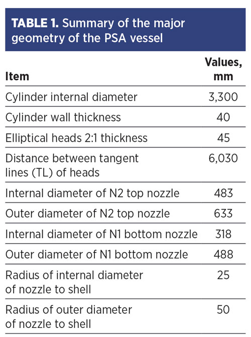
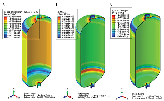
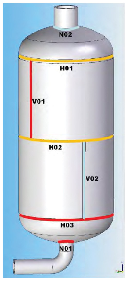
FE models. A simplified FE model of a PSA vessel (including top and bottom nozzles) was generated, as shown in FIG. 1, and a summary of vessel geometry is presented in TABLE 1. The model consisted of 37,164 quadratic brick elements with a global mesh seed size of 50 mm, a minimum of 16 elements around a circle, and three elements through the wall thickness.
This model was then treated as a generic model that was used for other vessels; therefore, the geometry, boundary conditions and loads remained the same.
Boundary condition and loading condition. A kinematic constraint was applied to the location of the vessel where the connection to the skirt would be. Constrained to an arbitrary reference point but free in the radial direction, the reference point (in turn) had all degrees of freedom constrained. Kinematic constraints were additionally applied to the top and bottom nozzles modeled. Both were constrained to individual reference points, centered flush with the end face of the nozzle but free in the radial direction. This allowed for the correct representation of the nozzle end loads (as system loads and bending moments could be applied as required) as well as constraints due to the continuous connection to pipework.
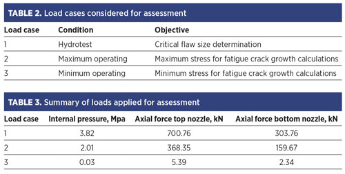
The loads considered for this assessment were self-weight due to gravity, internal pressure, and loading resulting from internal pressure, such as nozzle end loads (blow-off loads). No additional system loading was available, and thermal loading or thermal transients were not considered, which is likely insignificant, considering operating temperature.
TABLES 2 and 3 summarize the loading cases and the actual loads (e.g., pressure and axial stress) applied on the model. The basic material properties of ASTM A516Gr.70 for FEA were the same for all 12 vessels:
- Density of 7,850kg/m3
- Young’s modulus of 207 GPa
- Poisson’s ration of 0.3.
FEA result. Linear elastic stress analyses were performed based on a finite element model of PSA vessels so the stresses in the critical locations of interest where cracking was detected could be resolved correctly and accurately. However, the model was not designed to assess structural integrity of the entire vessel, such as inside the vessel, skirt, vessel support, etc.
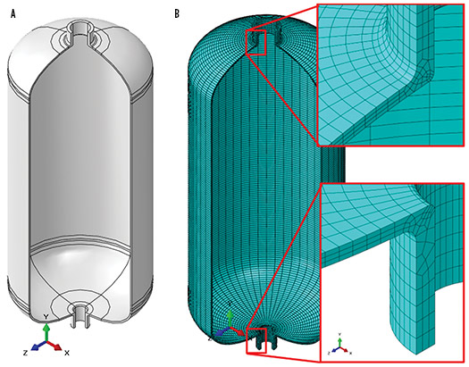
Views of a cross-section of the PSA vessel model for the hydrotest load case, hoop stress, von Mises stress and maximum principal stress are shown in FIG. 2.
The locations for the extraction of the stresses for the FFS assessment of the vessel for weld locations are N02 (top nozzle), N01 (bottom nozzle), H01 (top head weld), H02 (middle body weld), H03 (bottom head weld), V01 (upper vertical weld) and V02 (lower vertical weld), as illustrated in FIG. 3.
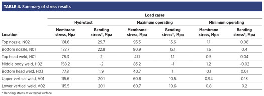
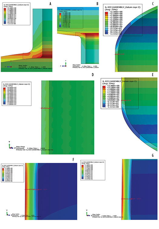
The through-thickness stress distributions of the welds selected for the assessment are shown in FIG. 4. The stress component was chosen depending on the crack orientation with respect to the weld location (e.g., a hoop stress component for transverse cracks in circumferential welds and an axial stress component for transverse cracks in seam or vertical welds). These results have been summarized in TABLE 4 in terms of membrane and bending stresses, which are required for the fracture mechanics assessments.
FFS assessment. The FFS assessment and remaining life assessment for the crack-like defects found in the welds were carried out in accordance with guidance given in API579 and BS7910. The assessment included two major components:
- Determining the criticality of the defects using a failure assessment diagram (FAD)
- Calculating the remaining life of the most critical defect from each vessel.
Flaw geometry, location and orientation. The most critical defects were selected from the inspection reports based on the defects’ height and the ligament. The assumptions made for the FAD assessment were:
- The length of defects was same as the weld size (as shown in TABLE 5), i.e., wall thickness as the flaw lengths were not available.
- The defects are located at the highest stress area within the weld.
- Subsurface or embedded defects are characterized as elliptical cracks, and surface defects are characterized as semi-elliptical cracks.
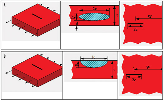
The generic geometry of the elliptical embedded flaw and semi-elliptical surface flaw used in the FAD assessment are presented in FIG. 5.
In this assessment, the lengths (2c as indicated in FIG. 5) were considered having the same size as the weld size, and the crack depths (labelled 2a as an embedded crack, labelled “a” as a surface crack) were taken from the inspection report. Flaw locations and orientations were as specified by the inspection report. The flaw orientation was assumed normal to the weld.
Primary and secondary stresses. The primary stresses used for this assessment come from the “hydrotest” loading condition shown in TABLE 4 of the FEA results.
The PSA vessels were subjected to post-weld heat treatment (PWHT); therefore, secondary weld residual stresses in accordance with BS7910 for PWHT conditions have been applied. For flaws that are aligned parallel to the weld, the residual stress can be assumed as 30% of the yield strength of the parent material at room temperature. For flaws that are aligned transverse to the weld, the residual stress can be assumed as 20% of the lesser of the yield strength of the parent and weld materials at room temperature.
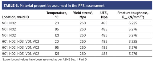
Material properties. The tensile properties and fracture toughness for the vessel material (SA516 Gr. 70) used for the FFS assessment are summarized in TABLE 6.
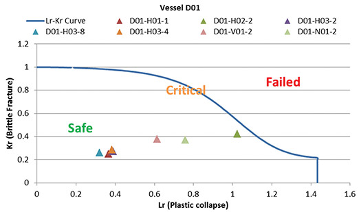
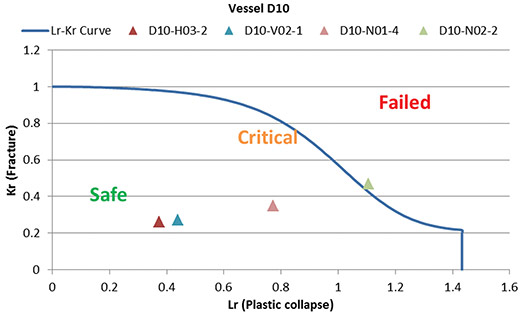
FAD assessment results. The cracks found in each vessel have been assessed using an FAD. Selected FADs are shown in FIGS. 6 and 7. The assessment revealed:
- Most of the cracks assessed for vessels D01–D12 fell within the FAD envelope; therefore, they are acceptable for continued operation.
- The crack, D10-N02-2 (the crack in the top nozzle weld in the D10 vessel) was outside the FAD envelope, indicating the current crack size was unacceptable (FIG. 7).
- The crack D01-H02-2 (the crack in the middle body weld in the D1 vessel) was inside the FAD envelope, but with a very small margin, as shown in FIG. 6. This implies a potential risk of this crack being critical in the near future, even if its current crack size is acceptable.
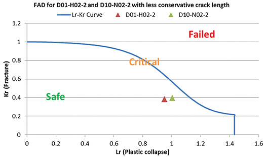
Refined FAD assessment. The crack lengths used for the initial FAD assessments were determined based on a conservative assumption of equaling them to the weld size. The FAD assessments for the most critical cracks, D01-H02-2 (Vessel D01) and D10-N02-2 (Vessel D10) were refined by using the measured crack lengths, which were provided after the initial assessment.
The measured length for D01-H02-2 and D10-N02-2 were 16 mm and 12 mm, respectively; however, the a/c (height-to-length) ratio exceeded the valid range, therefore the closest valid ratio of 0.97 was applied. The refined assessment revealed that both cracks fell inside the FAD envelope (as seen in FIG. 8), indicating that both cracks were acceptable.
REMAINING LIFE ASSESSMENT
Damage mechanism and crack growth. The PSA vessels have been subjected to a cyclic loading frequency of 100 loading cycles per day. This cyclic loading operation was believed to be the major driving force of the crack growth, so a fatigue cracking mechanism was applied in the remaining life assessment. The remaining life is determined when the crack continues to grow until it reaches critical flaw size.
Multiple scenarios exist for how the crack could grow to reach critical flaw size:
- The initial flaw could grow from being an embedded flaw, to breaking the surface, then through the wall before reaching its final critical flaw size.
- The initial flaw could grow from being an embedded flaw, to through the wall to reach its final critical flaw size.
- The initial flaw could grow from being an embedded flaw, to breaking the surface, which could then represent its final critical flaw size.
- The initial flaw could grow from being an embedded flaw to reach its final critical flaw size and still be embedded.
- The initial flaw could grow from being a surface flaw, to through the wall to then reach its final critical flaw size.
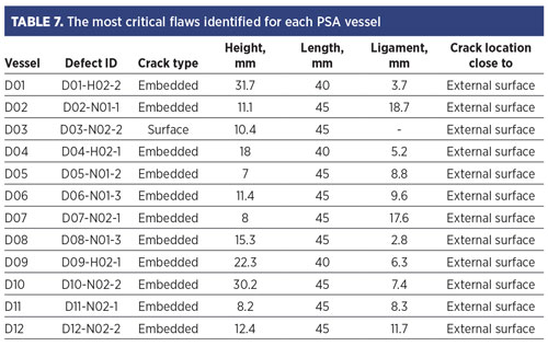
The assessments focus on the state of the vessel before leakage occurred; in other words, the crack may keep growing as an embedded or surface flaw before the depth penetrating the wall thickness of the vessel. Therefore, under current operating loads, the remaining life of a vessel was defined as the remaining time before the most critical flaw reached either its critical flaw size (i.e., outside of the safe area in the FAD) or prior to being developed as a through-wall thickness crack (i.e., before leakage occurs). The most critical defects from each vessel, as summarized in TABLE 7, were considered for the remaining life assessment of the vessels.
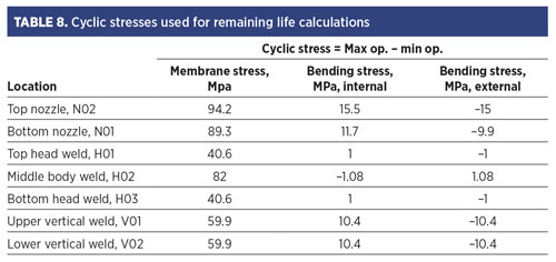
Cyclic stresses. Based on the maximum and minimum operating stresses shown in TABLE 4 of the FEA results section, the cyclic stresses required for the fatigue crack growth assessment were calculated and are summarized in TABLE 8.
Fatigue crack growth model. The fatigue crack growth analysis was carried out using the Paris law (Eq. 1):
(da/dN) = C(ΔK)m (1)
where:
da/dN = fatigue crack growth rate, mm/cycle
ΔK = Stress intensity range, MPa √m
C, m = Paris law coefficient and exponent.
C and m are the material parameters available from API 579 and BS 7910, which are applicable to weld steel joints in air environment conditions up to 100°C. C = 1.29 × 10⁻¹² and exponent, m = 2.88.
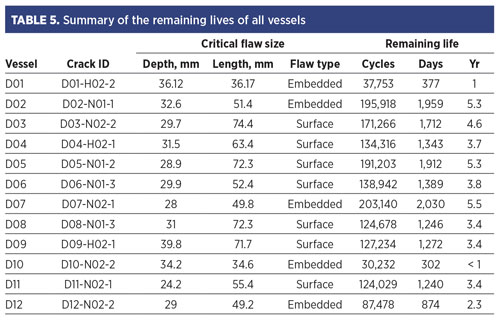
Results of remaining life assessment. TABLE 5 summarizes the remaining life assessment results from 12 vessels (D01–D12) in terms of remaining operating cycles, days and years. The remaining life in days and years were calculated based on the operating condition of 100 cycles per day.
In general, most of the PSA vessels will last more than 3 yr before the initial cracks reach their critical flaw size, whereas vessels D01, D10 and D12 have relatively shorter lives (i.e., 1 yr, < 1 yr and 2.3 yr, respectively).
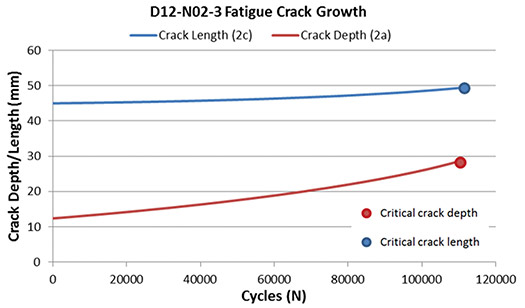
The graph in FIG. 9 shows an example of how the current cracks grow by fatigue prior to becoming critical.
Takeaways and recommendations. The FFS assessment and remaining life assessment were carried out for the PSA vessels D01–D12, where defect indications were discovered in the welds during the inspection. The main objective of the assessments was to determine whether the vessels with the defects were fit for service and how long the vessels can be operated. The following conclusions and recommendations were made from the assessment:
- The selected critical cracks assessed for vessels D01–D12 fell within the FAD envelope; therefore, the cracks are acceptable for continuing operation.
- The cracks in vessels D01 and D10 were found be the most critical.
- The remaining life of each vessel was determined based on the assumption that the current crack continues to grow by fatigue as a result of cyclic loading until it reaches critical flaw size.
- The remaining life of most of the PSA vessels (i.e., D02, D03, D04, D05, D06, D07, D08, D09 and D11) ranges from 3 yr–5 yr.
- Vessels D01 and D12 have relatively shorter lives: 1 yr and 2.3 yr, respectively. Vessel D10 has the shortest life: 302 d.
- It is recommended to prioritize vessels D10 and D01 for repair, particularly the top nozzle weld (N02 weld) in vessel D10 and the middle body weld (H02 weld) in vessel D01.
- If normal operating conditions change (especially the frequency of cyclic loading and maximum pressure), or there is a departure from the operating conditions assumed in this assessment that could be detrimental, it is recommended to carry out repeated assessments under these revised operating conditions to ensure the vessel remains fit for service.H2T
OHGEON KWON is a Principal Consultant and Structural Integrity Team Lead at Quest Integrity. Dr Kwon has more than 25 yr of experience and expertise in high-temperature creep, FFS and remaining life assessments for various components in the petrochemical, refining and power generation industries. He earned his PhD at Imperial College, London.
SANG-MO LEE has more than 26 yr of experience as a Fixed-Equipment Engineer at SK Energy. His main tasks include root cause analysis (RCA), troubleshooting, FFS evaluation, maintenance procedures and technical support for the refining and petrochemical business. He earned a BS degree in mechanical engineering and is qualified as a professional engineer for welding and metallurgy by the South Korean government.
Related Articles
Connect with H2Tech
