Articles
Eight guidelines for planning a H2 blending pilot at a power generation facility
POWER AND UTILITIES
N. KLEIN and M. REUSSER, Burns & McDonnell, Kansas City, Missouri
H2 is emerging as a pivotal fuel source for utilities seeking to decarbonize their existing power generation assets, and it is easy to understand why. H2 is a clean-burning fuel that can be produced from a variety of zero- or low-carbon sources. When combusted, it releases no carbon-related emissions, making it a front-runner to reduce the volume of natural gas relied on as fuel. It also has the potential to help existing power generation assets transition into the rapidly evolving decarbonization landscape.
However, before committing funds to full-scale H2 retrofits, utilities must first consider some fundamental questions. How will plants respond when H2 is introduced as a fuel source? What modifications will the system require to utilize H2? How will the introduction of H2 affect performance and emissions?
To learn the answers to these and other questions, some utilities have begun pilot programs to blend H2 fuel into the natural gas supply at existing gas turbine and reciprocating engine sites. These short-duration tests are designed to assess everything from equipment efficiency to the viability of environmental sustainability goals.
The protocols for these pilot tests are complex. Even a 1-wk pilot test can take 1 yr to plan, design and implement. Success depends, in part, on the ability to integrate the testing infrastructure with the existing operational system. The following are several key items to consider when developing a H2 pilot test (FIG. 1).
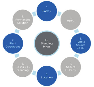
Safety comes first. H2 has some unique properties that must be considered. It is nontoxic, colorless and odorless. Because it is the first element on the periodic table, it is approximately 14 times lighter than air. H2 is also flammable in a wide range of air concentrations, making it easier to ignite than other fuels, if not handled safely. Interestingly, if a H2 source ignites, the flame burns on the ultraviolet portion of the light spectrum, making it nearly impossible to see. This factor could result in requirements for special flame detector equipment.
Other precautions are also essential for a safe and successful pilot test. For example, consider that the fuel systems at many existing power generation facilities were originally designed only for natural gas. Because H2 molecules are significantly smaller than methane molecules, leakage may occur through various flanges, gaskets and valves when H2 is introduced into these systems. Due to the potential presence of leaks, appropriate H2 leak detection will be necessary in any enclosed areas or areas with a potential ignition source.
Safety starts with planning and engineering design, including the performance of a hazard and operability (HAZOP) study and other safety reviews, long before H2 is introduced into the facility. A completed safety review helps facilitate assessment of the system design, operating and safety procedures, and emergency response plans. Additionally, the safety review assesses whether applicable codes and standards, such as the National Fire Protection Association (NFPA) 2–Hydrogen Technologies Code, are being followed appropriately.
If an identified hazard cannot be fully mitigated by elimination, substitution, engineering controls or administrative controls, personal protective equipment is used as the last line of defense when working with or around H2.
Original equipment manufacturer (OEM) coordination is essential. OEMs for gas turbines and reciprocating engines have the greatest knowledge about the H2 fueling capabilities and requirements of their equipment. OEMs can apply insights garnered from burning H2 in a lab environment to better understand the impact that H2-blended fuels have on equipment performance and combustion emissions. Their input is essential in developing effective test plans, including the rate at which the blend ratio of H2 to natural gas is adjusted.
OEMs are eager to participate in these discussions since they have a stake in the results. It is valuable to obtain more data about how in-service units function when an alternate fuel is introduced over a range of operating scenarios, both when retrofitting installed equipment and when designing future engine and turbine models with 100% H2 capabilities.
Determine the source and type of H2. For these projects, H2 is typically delivered by trailer in either a liquid or gaseous form. Onsite H2 generation is possible but usually not feasible for most pilot projects. Delivery via a local H2 pipeline may also be an option if a plant is close to the supplier’s distribution system, but this option also presents unique challenges that make it an unlikely source of H2 for a pilot test.
Today, many industrial gas suppliers are set up to provide H2 in relatively small quantities for short-term applications or on a long-term, recurring basis. For example, a single trailer delivery of liquid H2 for a typical industrial customer might be enough for a 6-mos supply. For these pilot power projects, however, a test may require as many as six gaseous or two liquid trailers for a weeklong testing operation. A high-level comparison between gaseous and liquid H2 deliveries is detailed in TABLE 1.
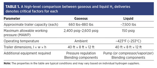
After determining the amount of H2 required for a test, the next step is to identify the source and type of H2 to be used. The type of H2 chosen impacts the design of the overall blending process. The equipment setup for gaseous H2 is much simpler than that for liquid H2. High-pressure gaseous H2 can be connected directly to the blending system, whereas liquid H2 must be vaporized and its pressure increased before it can be injected into the fuel system. While liquid H2 can be stored at significantly higher quantities and lower pressures than its gaseous form, it is extremely cryogenic, meaning it must be kept at an extremely low boiling point temperature near –423°F (–253°C).
From a pilot testing perspective, the color of H2 used is less relevant since it does not impact the equipment’s operational functionality during the short test period. The designated H2 color (green, blue or gray) is indicative of the carbon emissions created during its production. Today, most H2 suppliers typically provide gray H2, which is produced using traditional methods (e.g., steam methane reforming) for pilot tests.
Secure H2 early. Since pilot tests are predicated on timely deliveries of H2 and the large volume needed for the test duration, orders must be placed early. Even a single turbine or engine test can require a significant amount of H2 over a brief period. Determining the test volume required will help expedite coordination with industrial gas suppliers on H2 deliveries that could be limited by quantity and geographic location.
Logistics will evolve over time to address supply chain challenges as utilities consider H2 supply options that meet their long-term environmental and financial goals. Instead of sourcing H2 externally in the future, utilities could produce it onsite via the electrolysis of water. Water electrolysis is a mature technology process that utilizes an electrical current to divide water molecules into oxygen and H2. When coupled with wind, solar or other renewable energy sources to produce electricity, water electrolysis generates zero carbon dioxide (CO2) emissions. Until this method of H2 production becomes more widespread, expect a significant increase in liquid or compressed gas H2 deliveries to accommodate pilot testing.
Location. The NFPA’s rules for sitting H2 storage are detailed in NFPA 2–Hydrogen Technologies Code, which provides minimum setback requirements for both liquid and gaseous H2. Gaseous H2 system setbacks are based on storage pressure and piping size, while the setbacks for liquefied H2 systems are based on storage volume.
During the conceptual design phase, each pilot testing site should be evaluated to determine the appropriate placement of H2 trailers and other equipment to facilitate testing while maintaining the required spacing. NFPA 2 setbacks impact the transportation of H2 trailers in and out of the plant site, as well. Depending on the space constraints at the facility, this may also impact the choice of liquid or gaseous H2 for the test.
The placement of tie-ins and equipment for H2 blending matters. Tie-ins to the plant’s natural gas system must be located in ways that minimize exposure to existing components not originally designed for H2 usage. Adequate pressure, temperature and flow conditions per OEM requirements, along with pertinent safety devices, are also required in these locations.
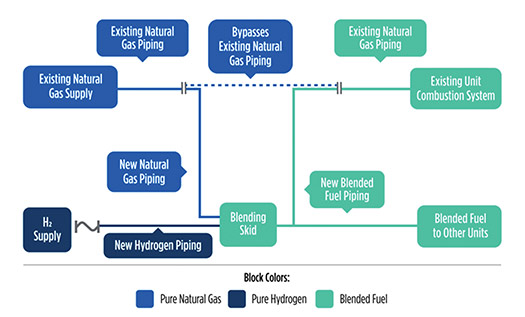
These pilot projects typically require two natural gas tie-ins: one to supply natural gas to the blending system, and the other at the point where the H2 and natural gas mixture from the blending system is injected into the existing fuel gas pipe. The blending system typically consists of a H2 transfer system, flowmeters and control valves (FIG. 2).
An important goal of these pilot tests is to learn how the gas turbines and reciprocating engines react to changes in fuel composition or incomplete mixing. For example, while it is understood that the introduction of H2 to a natural gas fuel stream changes combustion dynamics, less is known about how the equipment will respond to an imperfect mix of H2 and natural gas. These projects are expected to assess the equipment’s tolerance for these changes, as well as for various H2 and natural gas concentrations.
H2 blending pilot tests can impact other plant operations. H2 may also impact the operation of utilities, equipment and other systems in an existing plant. A balance of plant evaluation is necessary to determine H2 blending tie-ins, as well as any changes needed to piping, control systems, electrical infrastructure or safety systems, such as fire and gas detection. Impacts to other operating units at the site should also be considered when adjusting emissions controls for the tested unit(s).
Depending on where and how the pilot connects to the plant, operations may be affected in other ways, as well. For example, when working in a plant with multiple engines or turbines, it is preferable to isolate the H2 test to one unit while the other units are in an outage for the test duration. A pilot test that ties into the common fuel gas header may have a greater impact on overall plant operations than one tied directly into the unit being tested. The time and complexity needed to set up for the pilot test and restore the system after its completion must also be accounted for during the plan’s development.
Permanent conversion and permit reevaluation raise new questions. Utilities considering permanent H2 installations may face other unknowns. Permitting agencies’ reactions to pilot tests and future installations are uncertain since there is almost no precedent for them to follow. On one hand, the blended fuel will enable plants to lower CO2 emissions. On the other hand, permits were issued based on the use of the original, unblended fuel.
The main unanswered question is: Will permitting agencies allow blended fuels under existing permits, or will permit modifications be allowed? Now is the time to begin conversations with permitting agencies on the ramifications of potential permit changes related to H2 blending.
Takeaway. The source of H2, storage location and tie-in locations—while keeping safety first and foremost—are major factors that will be crucial to the successful completion of the pilot testing protocol.
The goal for each test may be different for every facility. Some may be interested in understanding H2’s impact on equipment performance, while others may be curious to learn how the presence of H2 impacts CO2 and nitrogen oxides emissions. Regardless of the test objective, a H2 blending pilot can provide insights into the potential challenges that must be overcome and the changes that must be made to current operations. Successfully navigating these challenges will set the stage for future, H2-based power generation innovations.H2T
NICHOLAS KLEIN is a Development Engineer at Burns & McDonnell with nearly 10 yr of experience in the power generation, gas and energy industries. He has led the mechanical design for multiple engineering, procurement and construction projects centered on reciprocating engine and turbine applications. He is actively involved in a H2 blending pilot that is scheduled to conduct testing in Q4 2022. Additionally, Klein was a key team member on the winning Ignite competition team focused on green H2. He earned a BS degree in mechanical engineering and an MBA from the University of Illinois at Urbana-Champaign.
MEGAN REUSSER is a Senior Development Engineer at Burns & McDonnell with more than 12 yr of industry experience. She has a diverse background in front-end project development, including process engineering, proposal management and cost estimation. These skills create a unique blend of both technical and commercial expertise that she uses to provide her clients with technical solutions that optimize process design and reduce energy consumption, CO2 emissions and overall costs. She specializes in technologies supporting decarbonization projects such as green H2 production, carbon capture and liquefied air energy storage. Reusser was named a Rising Star in Hydrogen Economist’s Women in Hydrogen 50. She earned a BS degree in chemical engineering and an MBA from the University of Kansas.
Related Articles
Connect with H2Tech
