Articles
Solid oxide electrolysis cell (SOEC): Potential technology for low-cost green H2
SPECIAL FOCUS: FUTURE OF HYDROGEN ENERGY
S. ROY and M. ETHAKOTA, Technip Energies India Ltd., Noida, India
Achieving net-zero emissions by 2050 to restrict global temperature rise to 1.5°C continues to be a significant challenge for the global energy sector. According to the International Energy Agency’s (IEA’s) Annual Report 2021, there will be a huge energy transition from fossil fuel to renewables to 2050: it is forecast that almost 90% of electricity generation will come from renewable sources, with wind and solar PV together accounting for nearly 70%. While there will be a significant shift towards electrification, some sectors will be difficult to electrify, such as steel, cement, chemicals, fertilizers, aviation, etc.
Hydrogen (H2), and specifically green H2 (H2 made without fossil fuels), can play a key role in decarbonizing these sectors.
H2 can contribute to energy security and environmental compatibility as an alternative energy carrier—the energy system has key features that include availability, economic production, transportability, transformability (into other forms of energy) and environmental friendliness. It has the potential to be used as fuel for power and transportation. Electricity and H2 form complementary options for transferring and storing energy for different end uses, offering much more flexibility in optimizing energy structures on a macro scale. Both are efficient and easy-to-handle and have near-zero emissions when used (considering non-fossil origins).
H2 combined with carbon dioxide (CO2) to produce liquid synthetic fuels may also contribute to a reduction in CO2 emissions. H2 or H2-rich liquid fuel (e.g., methanol) can be converted to electricity for transport purposes via fuel cells. Also, it can serve as a feedstock for various chemical reactions to produce a range of synthetic fuels and chemicals, potentially decarbonizing these sectors.
Global H2 production must rise from approximately 75 MMtpy to 500 MMtpy–700 MMtpy by mid-century to reach net-zero CO2 emissions targets. Coupling H2 production with renewables is a viable path to achieve this. More than 95% of today’s global H2 production is from carbon-based, CO2-emitting methods: natural gas steam methane reforming (SMR) and coal gasification.
Green H2 can be produced in several ways using renewable energy sources like solar, wind or nuclear (high- and low-temperature electrolysis, various thermochemical and photochemical processes, etc.). However, water electrolysis is the most effective technique and is capturing the market’s attention.
The electrolysis of water to produce H2 has been studied for the last 100 yr. However, at present, only less than 1% of H2 is produced from the electrolysis of water due to the high consumption of electrical energy required to separate the water molecule because water is a very stable molecule. Nevertheless, as renewable power costs have been decreasing significantly over the years, H2 production through electrolysis is encouraged, as this route is the most sustainable process for producing H2.
Several water electrolysis technologies have been developed throughout the years. At present, alkaline electrolysis (AE) and proton exchange membrane electrolysis (PEME) are proven as commercial technologies. However, solid oxide electrolysis (SOE) has attracted many to bring this technology to market to achieve better energy efficiency. Other water electrolysis technologies—like anion exchange membrane electrolysis (AEME) and protonic ceramic electrochemical cell electrolysis (PCECE), among others—are in the development or demonstration stages and are not discussed here.
Low-temperature electrolysis AE and PEME are operated below 100°C, whereas SOE operates at significantly higher temperatures. Despite their lower operating temperatures, high efficiency and technological maturity, low-temperature electrolysis cells cause high electrical energy consumption. Thermodynamically, the electrical energy demand to electrolyze water decreases as the operating temperature increases. Due to this, high-temperature electrolysis like SOE could achieve a 30%–40% reduction in electricity consumption if integrated with external process waste heat. Therefore, high-temperature solid oxide electrolysis cells (HT-SOECs) can produce the most cost-effective energy H2 compared with low-temperature routes like AE and PEME.
This article explores several opportunities to produce green H2, mainly focusing on SOEC technology and its advantages and challenges.
WATER ELECTROLYSIS TECHNOLOGIES
Electrolysis is the most straightforward approach now available to produce H2 directly from water. Water electrolysis is the dissociation of water using electricity to generate pure H2 and oxygen as a byproduct. In 1789, Jan Rudolph Deiman and Adriaan Paets van Troostwijk first demonstrated water electrolysis using an electrostatic generator. Then, in 1888, Dmitry Lachinov developed a method of industrial synthesis of H2 and oxygen via electrolysis.
Based on operating temperature, the electrolysis technologies can be categorized into low-temperature electrolysis (LTE) and high-temperature electrolysis (HTE).
Low-temperature electrolysis (LTE). Low-temperature electrolysis of water is presently the most mature method of green H2 generation. Low-temperature electrolysis is based on either a liquid or a solid polymer electrolyte. The water molecule is dissociated by applying an electrical current in both cases. The operating temperature is restricted to < 100°C.
Alkaline water electrolysis. Alkaline water electrolysis is composed of an anode and cathode separated by a gas-impermeable membrane. The electrolyte, usually an aqueous solution, comprises 20 wt%–40 wt% of sodium hydroxide (NaOH) or potassium hydroxide (KOH) concentration.
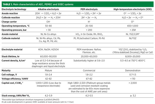
While employing electrical energy into two electrodes, water molecules dissociate at the cathode to give H2 and negatively charged hydroxide ions by reduction. At the anode, hydroxide ions oxidize, and oxygen and water molecules arise, releasing electrons. TABLE 1 provides further details.
Polymer electrolyte membrane water electrolysis. Polymer electrolyte membrane or proton exchange membrane (PEM) water electrolysis is a contemporary development. In this electrolysis, water is electrochemically dissociated into H2 at the cathode and oxygen at the anode, and a solid proton-conducting membrane separates the electrodes.
During electrolysis, oxidation of the water molecule leads to the formation of oxygen gas and positively charged H2 ions at the anode. The external power circuit facilitates the flow of electrons while the H2 ions move to the cathode through the semipermeable proton exchange membrane. At the cathode, these electrons recombine with the two protons to give one molecule of H2 by the process of reduction. The H2 gas generated has a very high purity of 99.99%. TABLE 1 provides further details.
High-temperature electrolysis (HTE). HTE is not yet commercialized, but systems have been developed and demonstrated on a laboratory scale. This technology holds promise for the future. HTE is an electrolysis method where steam is dissociated to H2 and O2 at temperatures between 650°C and 1,000°C. In electrolysis, system efficiencies increase with increasing operating temperatures. Low-pressure steam (LPS) can be used with reduced efficiency than the mentioned temperature. If this heat source is a clean one—such as geothermal, solar or nuclear—HTE produces H2 with nearly zero greenhouse gas (GHG) emissions.
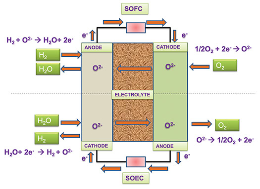
SOECs are fundamentally the reverse counterpart of solid oxide fuel cells (SOFCs). Refer to FIG. 1 for the reverse reaction.
DETAILED PROCESS SCHEME
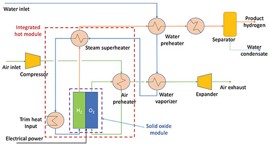
The typical flow scheme of the SOEC H2 production system is presented in FIG. 2. The system is designed to produce H2 by using electricity and water. The system’s main components consist of SOEC stacks in series and a balance of plant (BOP). The BOP includes a water pump, heat exchangers, steam generator, etc. Water is heated in a series of heat exchangers to recover the heat from the SOEC outlet gas stream. Preheated water is introduced to the steam generator to produce steam and then to the electric heater to superheat steam. To minimize electricity demand and improve SOEC system efficiency, steam is heated in multiple heat exchangers by the exiting H2 and oxygen streams. However, in case of availability of external steam, the scheme shown in FIG. 2 can be further optimized.
In the electrolyzer, steam is dissociated at 650°C–1,000°C at the cathode to form the H2 molecules and oxygen ions (water reduction reaction). The oxide ions migrate from the cathode to the anode and release electrons to the external circuit to become oxygen gas via an oxygen evolution reaction. High temperatures are required to thermally activate oxide ion migration and facilitate electrochemical reactions on both electrodes. As a result, the overall efficiency is improved.
- Cathode reaction: At the H2 electrode-electrolyte interface, the steam is split into H2 and oxygen ions (Eq. 1):
2 H2O + 4 e– } 2 H2 + 2 O2– (1)
- Anode reaction: Oxygen ions are drawn through the ceramic electrolyte, at the electrolyte-oxygen electrode interface, and oxygen gas generates (Eq. 2):
2 O2– } O2 + 4 e– (2)
The oxygen then flows along the anode while the H2—along with some steam mixture—passes along the H2 electrode on the opposite side of the electrolyte. Downstream of the electrolyzer, the H2-rich product stream is cooled down after exchanging heat with the inlet process stream, and then passes through a separator to separate H2 from the condensed water stream.
A fraction of the product H2 is recycled and mixed with inlet steam (5%–10% H2 in steam) to maintain reducing conditions and avoid oxidation of the nickel in the H2 electrode. As a result, HT-SOECs can be operated at high current densities that allow large production capacities using comparatively small cell areas. Practically, an electricity-to-H2 efficiency of about 90% [on a higher heating value (HHV) basis] appears to be realistically achievable.
High temperature is one of the concerns for heat resources during startup. To overcome that, self-heated (by electricity) standby SOECs can be helpful. While giving electricity due to resistance in the cell, Joule heating occurs, keeping the cell in comparatively hot condition and making it easier to use standby SOECs during startup. Conversely, H2 from an external source may be needed to keep the cathode in reducing conditions during standby mode.
Preheated air or steam can be used as a sweep gas to remove oxygen from the stack. The purpose of the sweep gas is to dilute the oxygen concentration and therefore decrease corrosion of the oxygen-handling components. Pure oxygen can be produced by the stack and would be a valuable commodity if satisfactory materials and coating could be developed to construct the oxygen-handling components.
SOECs use solid ion-conducting ceramics as the electrolyte, enabling operation at significantly higher temperatures. Potential advantages include high electrical efficiency, low material cost and the option to operate in reverse mode as a fuel cell or in co-electrolysis mode producing syngas [carbon monoxide (CO) and H2] from water steam (H2O) and CO2.
A key challenge is severe material degradation due to the high operating temperatures. Current research is focused on stabilizing existing component materials, developing new materials and lowering the operating temperature to 500°C–700°C (from 650°C–1,000°C) to enable the commercialization of this technology. Even LPS can be used to enhance commercialization. Furthermore, even if required, lowering the temperature below 500°C, integrating SOECs with high-temperature processes like conventional reforming, etc., can reduce combined H2 production costs.
TABLE 1 shows a comparison of SOECs with other commercial electrolysis technologies.
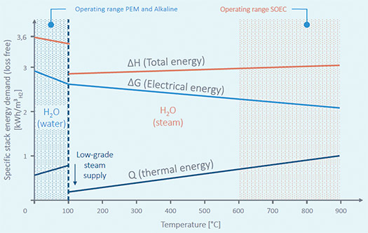
Thermodynamics of SOECs. From an overall efficiency point of view, electrolysis systems should be operated close to thermoneutral potential. In SOECs, it is possible to operate with a higher current density operation; therefore, a higher H2 production rate is possible. High-temperature electrolysis of water occurs in the vapor phase, so the total energy demand of electrolysis is reduced by the heat of vaporization. Vaporization can be done by using inexpensive thermal energy rather than electric energy. The Gibbs free energy of formation (for electrolysis reaction) decreases with increasing temperature—decreasing electricity input can be seen with increasing temperature in FIG. 3. Electricity input is ~35% lower than conventional electrolysis in high temperatures at approximately 800°C. The electricity input can be further lowered to ~50% when the temperature is increased to as high as 900°C.
The HT-SOE process is advantageous due to its high overall thermal-to-H2 efficiency when coupled with heat integration.
Once vaporization is achieved, high temperature is required to superheat steam to achieve high enough ionic conductivity in the electrolyte (steam). This extra heat can be provided by combining a waste heat source, recovering the sensible heat of the produced H2 and oxygen, and self-heating of the cell due to its inherent electrical resistance.
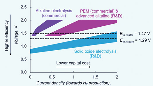
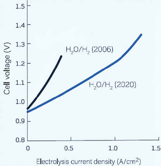
Temperature-related efficiency gains are far higher for SOECs when steam enters the stack at higher temperature using external heat sources. For splitting steam, SOECs operated at a thermoneutral potential (the potential at which the cooling effect from the endothermic electrolysis process is balanced by the Joule heating caused by the resistances in the cell) of 1.29 V will attain an electrolysis current density of ~1.5 A/cm2, whereas a PEM electrolyzer operated at a thermoneutral potential of 1.47 V attains a current density of ~0.5 A/cm2.
Lower cell voltage means lower operational costs (lower electricity demand per quantity of produced gas), while higher current densities are associated with lower capital costs as fewer electrolyzers are needed to achieve the required capacity for gas production when compared with low-temperature electrolyzers. Therefore, the economic motivation for the wider adoption of SOEC technology remains high (FIG. 4).1
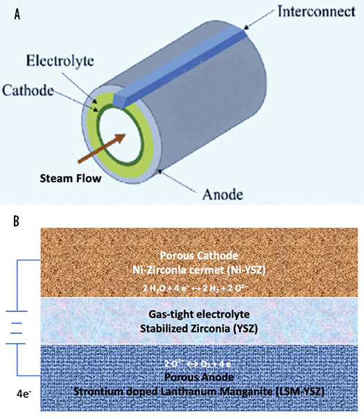
SOEC materials selection. In the SOEC unit, the electrochemical cell is the main electrolyzer component in which the electrochemical reaction occurs. It is composed of three ceramic layers: a dense electrolyte and two porous electrodes (cathode and anode, where H2 and oxygen are respectively produced) placed on both sides of the electrolyte. Given the high operating temperature range, the electrochemical cell is made of ceramics (solid oxide membrane electrolyte). For example, Y2O3-stabilized ZrO2 [yttria-stabilized-zirconia (YSZ)] acts as a gas separator and electrolyte. It is used where oxygen ions start migrating from cathode to anode when a voltage is applied. As a result, they show superior ionic conductivity at elevated temperatures.
The electrodes must be both electron and oxide ion-conducting, and maximizing the active surface area is essential for efficient operation. For the H2 electrode, a cermet (combination of ceramic and metal) of nickel and YSZ is often used with ~30% porosity, whereas a lanthanum strontium manganite (LSM)-YSZ mix is utilized for the oxygen electrode. Materials of different layers are shown in FIG. 5B.
Commonly used SOEC materials are earth-abundant materials, such as yttria and zirconia, which have attracted the use of SOECs. Solid oxide cells providing 1 TW of power in fuel cell mode would require just 1 mos worth of global ZrO2 production and 21 mos worth of Y2O3. In contrast, the same power provided by a PEM fuel cell system would require 53 mos worth of global Pt production.2
SOEC configuration. Single cells are the smallest units of SOEC and can be in either tubular configuration or planar configuration, as shown in FIG. 5. In the tubular SOEC, steam is fed through the inside of the tube and reduced to H2 gas and oxygen ions. The oxygen gas is extracted from the outer layer of the tubular SOEC.
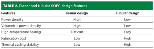
Compared with planar SOECs, the tubular SOEC exhibits higher mechanical strength and facilitates sealing. Tubular SOECs have the specific advantage of high-pressure operation over a planar configuration, although the interconnector design is a challenge (FIG. 5). Despite the larger sealing length between the anode and cathode compartment, the planar cells have better manufacturability and higher electrochemical performance.
The planar SOEC system performed better than its tubular counterpart due to its uniform distribution of gas species on planar SOECs, as well as easier mass production of planar cells—the planar SOEC system configuration is advantageous and should be further investigated. TABLE 2 shows some features of planar and tubular SOEC design.
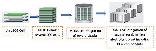
Cell-to-system configuration. To increase the production rate, the active area of the electrolyzer should be increased. By increasing the single cell dimension, it is challenging to increase the active area; so, many single cells are connected to build a stack. Other than cells, a stack consists of metallic interconnects, glass sealings, flow channels, etc. Several stacks build a module, and several modules build an SOE system of the desired area to achieve the desired production rate.
FIG. 6 illustrates the typical SOEC system configuration from cell level to plant level.
SOEC CHALLENGES AND ADVANCEMENTS
Challenges. The main challenge of SOEC technology that requires further improvement remains the lifetime of electrodes (particularly H2 electrodes), which are limited by degradation and the long-duration performance of the cells.
One of the main causes of cell degradation is the effect of impurities. In H2 electrodes, silica-containing impurities can block the electrocatalytically active sites by nonconducting phases, causing degradation and increased polarization resistance. However, cell degradation reduces if the quality of stack inlet gas is maintained.
For H2 electrodes during long-term operation at high over-potentials (~300 mV), the percolating nickel (Ni) network closest to the electrolyte is destroyed. Ni migrates from the electrolyte electrode interface to the support layer, resulting in irreversible loss of electrochemical performance. For future improvements of SOECs, this must be addressed.
High temperature is also a leading challenge associated with thermal expansion mismatch among different layers and diffusion between layers of material in the cell. Reducing stack operating temperature minimizes interconnect corrosion and the reaction between different stack components.
Challenges also remain in pressurized operations. Low-pressure SOE operation has the advantage of using easily available low-pressure steam at a comparatively lower temperature than that of high-pressure steam. Conversely, pressurized operation can provide several benefits (e.g., pressurization can increase cell power density and reduce the size of auxiliary components). The development of manufacturing techniques and assembling large area cells can reduce the overall cost of a commercial plant.
Advancements. Developments continue in the field of SOECs. Some advancements towards the enduring future of SOECs are discussed here.
Cell level improvement: Current-voltage curves recorded in steam electrolysis reveal that the initial performance of SOECs has increased by more than a factor of 2.5 over the past 15 yr (FIG. 7) due to a drop in area-specific resistance from 0.71 ohm.cm2 to 0.27 ohm.cm2 at 750°C. This has been achieved through modifications like improved cell layers’ processing, especially the H2 electrode.
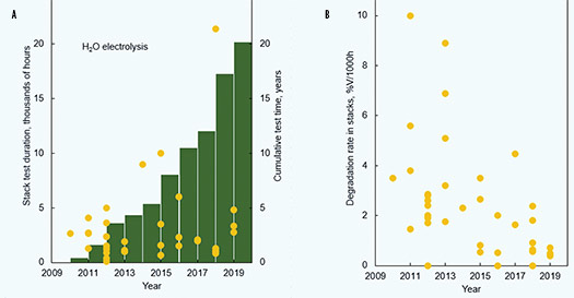
Cell degradation rates tend to decrease over time by a factor of 100 over a 10-yr period. From 2005–2015, cell tests conducted at a current density of 1 A/cm2 (all cells were supported by a Ni-YSZ electrode and had an active area of 16 cm2) found a decrease in long-term degradation rate from ~40%/1,000 hr to ~0.4%/1,000 hr for steam electrolysis.3 Conversely, alkaline electrolyzer degradation rates are at 1% per 10,000 hr—to reach this level many more improvements are required for SOECs.
Stack level improvement. SOEC stack performance is determined by the performance of cells and other stack components. The properties of each component change during long-term operation under the influence of high temperature. FIG. 8 shows improvement in stack performance from 2009–2019. For steam electrolysis, the stack lifetime tested was limited to < 4 mos in 2009, whereas stack lifetimes of nearly 2.5 yr were experimentally demonstrated in 2019. This is mainly due to an increase in stack durability—SOEC stacks are now less prone to sudden performance failure and degrade less rapidly.
Integrating the SOEC and the heat recovery unit remains a challenge. In addition, the efficiency and cost of the overall plant must be considered for design optimization. In the next section, potential integration schemes are discussed.
SOEC HEAT INTEGRATION WITH WASTE HEAT SOURCES
SOECs operate with high efficiency, especially if fed with high-temperature waste heat. The electrochemical conversion of water permits the storage of both heat and electricity in the produced H2 form. Green H2 produced by SOECs can be further processed into synthetic natural gas, methanol, green ammonia, etc., and thermally integrated with a wide range of exothermic chemical syntheses, resulting in further efficiency improvements. Heat integration is also possible with energy sources like nuclear reactors, coal-fired power plants, biomass, domestic waste incinerators, etc. Some of them are discussed here.
SOEC heat integration with diesel engines. Exhaust gas is a high-grade waste heat with temperatures that can exceed 500°C for diesel engines. Therefore, if a diesel engine is integrated with the SOEC system as a heat recovery steam generator (HRSG), it will significantly reduce the power consumption of the SOEC.
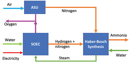
Coupling SOEC and ammonia (NH3) production plants. NH3 synthesis is an exothermic chemical reaction at relatively high temperatures and pressure (FIG. 9), so a large amount of heat is available for recovery in the plant’s energy balance. In addition, the produced H2 can be used as feed for NH3 production if mixed with a proper amount of nitrogen (Eq. 3).
1/2N2 + 3/2H2 } NH3
∆H298K = –45.7 kJ/ mol (at standard condition) (3)
System integration with an SOE and an NH3 plant by the Haber-Bosch process operated at high pressure (150 bar–200 bar) and temperature (300°C–500°C) is possible. The ammonia reaction can supply a significant amount of heat energy required by the electrolysis reaction, considering that for each ammonia synthesis, 1.5 mols of H2 are needed.
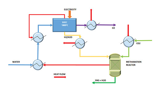
Heat integration of high-temperature electrolysis and methanation. The heat of the exothermic methanation reaction can be used entirely for the evaporation of the process water for electrolysis.
The methanation reaction catalyzes H2 with CO or CO2 into methane [synthetic natural gas (SNG)] and water (Eqs. 4 and 5).
CO + 3H2 } CH4 + H2O
∆H298K = –206 kJ/ mol (4)
CO2 + 4H2 } CH4 + 2 H2O
∆H298K = –165 kJ/ mol (5)
The exothermic reaction heat of methanation, the cooling of the product stream after methanation and the heat quantity generated by overvoltage (exothermic operation) are greater than the required heat quantity for vaporization and preheating reactant water. Therefore, high efficiencies are achieved by coupling high-temperature electrolysis and methanation (FIG. 10).
Versatile application of SOECs. SOECs can operate reversibly, enabling efficient cyclic conversion between electrical and chemical energy and providing long-term and high-capacity energy storage. In fuel cell mode operation, electricity is generated by oxidizing fuels. In SOEC mode, electricity generates H2, syngas, etc.
Development is ongoing to directly produce specialty and commodity chemicals other than green H2. For example, syngas can be produced from co-electrolysis of H2O and O2 using high-temperature SOECs. Syngas can then be converted into a diverse range of chemicals by subsequent catalytic reactions with varying H2:CO ratios. SOECs are also capable of splitting CO2 into CO and O2. Ammonia production by SOECs sending air and steam into the electrolyzer is under development, currently at very low yield. However, ammonia can be used as fuel while operating in SOFC mode for use in marine applications—this is also in development. This versatility in operation makes SOECs superior to other electrolysis modes of operation.
Takeaways. Reaching net-zero targets calls for significant changes in the ways the energy industry operates, and we are witnessing the movement in that direction. It is widely accepted now that H2 molecules have the potential to achieve the deep decarbonization of our energy industry, provided we can produce H2 more sustainably and cost-effectively.
Opinions vary around the globe on how to reach an ambitious green H2 cost of $1/kg. We know that the cost of renewable power is playing a significant role in the overall production cost of green H2, even though electrolyzer technology is one of the key barriers. Several green H2 projects are being announced around the globe. Alkaline electrolyzers (AE) are in the lead in terms of capacity, which is well-proven and price competitive, followed by PEM electrolyzer technology. Solid oxide electrolzyers are at a small-scale demonstration level. These technologies have achieved enormous improvements driven by advances at the cell, stack and system levels.
Some specific features make SOE technology unique compared to other commercially proven technologies, such as AE and PEME. For example, SOECs operate at 700°C–850°C, and the thermodynamically water split reaction requires a lower Gibbs free Energy (ΔG) at such a high-temperature, making this process highly efficient. Moreover, integrating an external waste heat source like low-pressure steam from an industrial source can help lower electricity demand, depending on the supply temperature. In addition to green H2 production, the same technology can be applied to various other processes directly producing end products like ammonia, methanol, SNG, etc.
The main electrolyzer components, like electrolytes and electrodes, are made of ceramic materials due to the high operating temperature. These SOEC materials are earth-abundant, so scaling up will not pose any challenge in terms of materials availability. Also, the possibility of SOECs working in reversible operation so a single unit allows for both energy storage and generation permits a complete green power plant to achieve zero-energy building and carbon neutrality targets.
Commercial SOEC electrolyzers are at the kW level, and demonstration units larger than 3 MW are under execution. To see the full potential of SOEC technology, much lower levels of cell degradation at higher current densities must be demonstrated. Moreover, to achieve commercial scale-up, further work is needed in manufacturing and assembling cells to reduce the unit’s overall cost.H2T
ACKNOWLEDGEMENT
The authors wish to express their sincere thanks to Thibault De-Sorbier, Process Technology Expert, Technip Energies Paris for his valuable suggestions and guidance.
REFERENCES
1 Anger, S. and D. Trimis, “Potential of thermally integrated high-temperature electrolysis and methanation for the storage of energy by Power-to-Gas,” International Gas Union Research Conference, Copenhagen, Denmark, 2014.
2 Bianchi, F. R. and B. Bosio, “Operating principles, performance and technology readiness level of reversible solid oxide cells,” Department of Civil, Chemical and Environmental Engineering, University of Genoa, Genoa, Italy, 2021.
3 Brisse, A. and J. Schefold, “High temperature electrolysis at EIFER, main achievements at cell and stack level,” Energy Procedia, Vol. 29, 19th World Hydrogen Energy Conference (WHEC) 2012.
4 Cinti, G., D. Frattini, U. Desideri, E. Jannelli, R. Cioffi and G. Bidini, “Coupling solid oxide electrolyzer (SOE) and ammonia production plant,” 6th European Fuel Cell Piero Lunghi Conference, Naples, Italy, December 2015.
5 Fu, W., W. Lei, O. Yangliang, L. Xuanmiao, Y. Jinliang, L. Xingjiang and Z. Yingying, “Thermodynamic analysis of solid oxide electrolyzer integration with engine waste heat recovery for hydrogen production,” Case Studies in Thermal Engineering, Vol. 27, October 2021.
6 Hauch, A., K. Brodersen, C. Ming, et al., “Abstract of a decade of solid oxide electrolysis improvements at DTU Energy,” IOPscience, 2017.
7 International Atomic Energy Agency (IAEA) Series, “Hydrogen production using nuclear energy,” 2012.
8 Jensen, S. H., X. Sun, S. D. Ebbesen and M. Chen, “Pressurized operation of a planar solid oxide cell stack,” Fuel Cells—From fundamentals to systems, February 2016.
9 Kamlungsua, K., P. C. Su and S. H. Chan, “Hydrogen generation using solid oxide electrolysis cells,” Fuel Cells—From fundamentals to systems, December 2020.
10 Mogensen, M. B., “Thermodynamics of high temperature H2O and CO2 electrolysis,” Department of Energy Conversion and Storage, Technical University of Denmark, Lyngby, Denmark.
11 Online: https://figshare.com/articles/dataset/Solid_oxide_electrolysis_stack_tests_2010-2019/12137112/1
12 Online: https://www.sciencedirect.com/topics/engineering/high-temperature-steam-electrolysis
13 Posdziech, O., “Production of renewable hydrogen and syngas via high-temperature electrolysis,” Sunfire, 2021.
14 Schmidt, O., A. Gambhir, I. Staffell, A. Hawkes, J. Nelson and S. Few, “Future cost and performance of water electrolysis: An expert elicitation study,” International Journal of Hydrogen Energy, Vol. 42, Iss. 52, December 2017.
15 Sohal, M. S., J. E. O’Brien, C. M. Stoots, M. G. McKellar, E. A. Harvego and J. S. Herring, “Challenges in generating hydrogen by high temperature electrolysis using solid oxide cells,” Idaho National Laboratory (INL), March 2008.
16 Vesborg, P. C. K. and T. F. Jaramillo, “Addressing the terawatt challenge: Scalability in the supply of chemical elements for renewable energy,” RSC Advances, Iss. 21, 2012.
SUKLA ROY is the Deputy Chief Engineer in the Process and Technology department of Technip Energies India Ltd. She has 17 yr of experience in the oil and gas industry, including more than 15 yr of experience in the H2, syngas and HCNG fields. She has extensive experience as a process lead in several basic engineering, detailed engineering and licensed engineering, procurement, construction and commissioning (LEPCC) projects. Previously, Roy worked with EIL as a process engineer. She holds an M.Tech degree in petrochemicals and petroleum refinery engineering and a B.Tech degree in chemical engineering from the University of Calcutta.
MARUTHI ETHAKOTA is Head of the Process and Technology department of Technip Energies India Ltd. In this position, he is responsible for Process and Technology departmental operations of all three Technip Energies India centers located in Delhi, Mumbai and Chennai. He has 26 yr of experience in the process and technology segments, and has been closely associated with the H2 molecule for 20 yr. In 2002, he joined the process department of Technip Benelux B.V in the Netherlands and has executed several H2 and syngas projects worldwide. He also worked as Product Development Manager for Technip Benelux for H2 and syngas technologies, where he was closely involved in developing new technologies for the H2 and syngas product line. Ethakota earned an MS degree in chemical engineering from Indian Institute of Technology, Kanpur, India.
Related Articles
Connect with H2Tech
