Articles
A case for online continuous performance monitoring
Maintenance and Reliability
T. GRESH and P. KUMAR, Flexware Inc., Grapeville, Pennsylvania
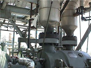
As part of a debottlenecking procedure, a refinery in Oklahoma (U.S.) was interested in analyzing its hydrogen (H2) recycle compressor (FIG. 1) performance, thinking it may need rerating to improve plant capacity.
The compressor string consists of a small barrel compressor and a condensing steam turbine driver. Of primary concern for data accuracy were the flowmeters and obtaining an accurate gas analysis. Accurate data was a special concern since completing a power balance does not provide confirmation of calculation results. Since the steam turbine is a condensing unit, the turbine power cannot be assessed directly and the turbine power is assumed to be equal to the power of the compressor it is driving.
Special care was taken to ensure accurate data. Pressure differential data from the compressor gas flowmeter was read directly and then used to calculate the flowrate to the compressor. The same was done for the turbine flowmeter. Multiple gas samples were taken to ensure redundancy. Typically, a gas sample should be taken at the inlet and discharge of the compressor, both before and after the test data is recorded. All gas samples should provide the same results, otherwise the gas sampling technique is ineffective.
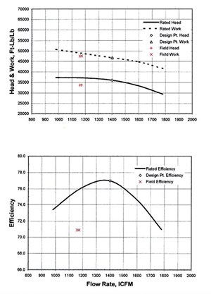
Compressor work input. The performance test had to be repeated several times before satisfactory results were obtained. After completing the first test, the plotted data showed a significant deviation between the compressor work input and the actual calculated value. Accordingly, the results were thrown out and the test repeated until the calculated work input was within reasonable proximity to the original equipment manufacturer’s (OEM’s) predicted work input (FIG. 2).

Compressor work input is the energy the compressor impellers put into the gas, represented by a temperature rise. This temperature rise or work input is present regardless of any inefficiencies in the compressor, such as worn internal seals or build-up or blockage inside the compressor. Unless there is serious damage to the impeller blading, flow swirl or other physical impeller damage, the work input will always be per predicted values. So, plotting calculated work input vs. predicted work input is an excellent method of indicating the accuracy of the data used for analysis, as well as the calculation method itself.
Gas sampling. The problem with the original test in this case was in the gas sampling technique. While the bulk of the gas is H2, there are small quantities of heavies in the gas (e.g., hexane, propane, butane). Even a small fractional error in the measurement of these heavies can upset the final mixture and have significant effects on efficiency and power values.
For the first few tests, the gas sample container was not completely purged or heated. It is necessary to completely purge the testing container of any residual gas or any condensable that may have adhered to the container walls. Heating the gas container and insulating it will minimize this issue. If not heated to the gas stream temperature, then the heavy components will condense on the container walls.
Additionally, prior to running the gas sample through the gas chromatograph in the laboratory, the gas must be heated again to the process gas stream temperature or higher to ensure any condensation has been vaporized. Even in a short period of time, the sample container will cool and the heavies in the gas sample will condense on the relatively cool container walls. If the container is not heated, the small fraction of heavies that have condensed on the container walls will not be accounted for by the gas chromatograph and the sample result is in error.
Another concern is leaks in the gas sample container, mainly the valves. H2 molecules are much smaller than the heavier gases like propane and hexane and will leak at a faster rate, thereby leaving the gas mixture in the bottle with a smaller percentage of H2 than the actual gas mixture in the process stream. So, checks for leaks in the sample bottle must be conducted—with H2, if possible—and it must be assumed a leak may still remain somewhere. Any delay should be avoided from the time the sample is taken to when it is processed in the lab to minimize the effect of any possible leaks.
Of course, an in-line gas chromatograph will solve these gas sampling issues.
The compressor was determined to be operating at ~71% efficiency, ~5 % below predicted values. The turbine was operating at ~44 % efficiency, ~10 % below its predicted value.
While the data showed that the equipment required maintenance to return to design operating conditions, the data also revealed that the compressor was operating at midrange and did not require a rerate, saving the refinery a lot of money, time and effort.
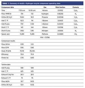
With the extra head in the compressor and extra power from the turbine available following proper maintenance, the higher pressure rise would provide the desired throughput, as shown in TABLE 1.
Knowing the performance of rotating equipment can provide key learnings. Knowing where the compressor is operating on the curve is valuable information. In this case, it was found that the compressor was not the bottleneck, and a rerate was not necessary as originally expected.
Note that the compressor power is identical to the steam turbine power. The compressor power was used as input data for the steam turbine calculation to determine the exhaust conditions of the condensing steam turbine. The accuracy of test was assessed by matching work input with the OEM performance curve.
About the author

TED GRESH serves as the President of Flexware Inc. For more than 50 yr, he has been involved in the design and field-testing of compressors and steam turbines, troubleshooting various field problems including performance problems, rotor dynamics issues, impeller failures and seal problems. In addition to numerous papers and magazine articles, he has published a book on the subject of compressor performance, and has several patents related to turbomachinery. Gresh received a BS degree in aerospace engineering from the University of Pittsburgh in 1971. The author can be reached at mtgresh@flexwareinc.com

PAVAN KUMAR is a Flexware aerodynamist and software tools coding and development engineer. He is involved with the development of compressor aerothermodynamics tools for centrifugal compressor design, field testing and performance estimations of compressors per PTC codes. Kumar has also been involved in the design of industrial reciprocating compressors, screw compressors and turbo compressors, including refrigeration compressors. He received his MS degree from the National Institute of Technology, India, specializing in the design of thermal power equipment. He has attended Texas A&M short courses on compressor aerodynamics and has conducted hands-on turbomachinery training.


