Articles
A synopsis of hydrogen generation
Process/Project Optimization
V. K. KHANNA, Engineering Consultant, Gurugram, India
Hydrogen (H2) has found use in various spheres of the energy industry. The fertilizer and petroleum industries have utilized H2‘s potential in wide applications, from direct use in ammonia synthesis to its aid in the secondary processing of petroleum products. Other industries include food processing, such as the hydrogenation of oils and fuel cell batteries. The pharmaceutical industry is also progressing in using H2 for drug formulations. Innovative requirements have led to quantitative and qualitative demand, thereby calling for an improvement in processing technologies.
The author has experienced the implementation of two H2 plants, one based on Linde’s technology with various interactive sessions and the other by Topsoe. The H2 plants were based on naphtha steam reforming, and the related details are shared in this article, including information on other processes used today. Major investments and research have been made on steam reformer plants.
The evolution of processes. For nearly seven decades, H2 generation has predominantly been the domain of the fertilizer and petroleum industries. The fertilizer industry drove commercial production due to nitrogenous fertilizers being made from ammonia (NH3) directly synthesized from H2 and nitrogen. Fritz Haber and Carl Bosch were the first to develop viable H2 generation in the early 20th century.
The first 3-ton per day (tpd)−5-tpd NH3 plant was built in 1913 in Germany. Since then, the technology has evolved, improving processes and capacity. H2 generation has followed the same pattern with various industrial applications. H2 demand is growing for the hydrocarbon processing industry (HPI) as the conversion of heavier products into more useful material increases. The hydrocarbon processing and fertilizer industries want high-capacity plants, and the HPI requires high-purity H2 (99.96%) for economic reasons. For other industries, it may not be as crucial.
Concept and processes. The various processes in use are:
- Steam reforming of naphtha or natural gas. Steam naphtha and natural gas reforming are catalyst-based processes in which an endothermic reaction forms H2 at 380°C and a pressure around 43 bar.
- Partial oxidation of coal (Koppers-Tedzec coal gasification process) or heavy oils. This process involves an exothermic reaction in which carbon monoxide (CO) reacts with water to produce carbon dioxide (CO2) and H2. This is a faster reaction than steam reforming.
- Steam iron. The steam iron process works by decomposing steam via a reaction with iron oxide.
- Methanol reforming for H2 generation. Methanol steam reforming using Group VIII−Group XII metals for high yields of H2 is in use. Various alternative metal catalysts are used to enhance the yield. Much research is underway to make it a viable and acceptable process for small to larger outputs. However, naphtha and natural gas steam reforming output levels are not yet achievable.
- Water electrolysis. Electrolyzers use electricity to split water into H2 and oxygen. This technology has greatly developed recently and is available commercially; further development is continuing for better results. Electrolyzers vary in size for small-scale production of H2 to large-scale facilities.
- Complex splitting of water and solar thermochemical H2. Thermochemical water splitting uses high temperatures from solar or nuclear power reaction’s waste heat and chemical reactions to produce H2 and oxygen from water. This is a long-term technology pathway that could result in low or no greenhouse gas (GHG) emissions.
- Biomass gasification. Biomass gasification uses a controlled process using heat, steam and oxygen to convert biomass to H2 and other products. This process is in the developmental stage.
- Biomass-derived liquid reforming. In this process, liquids from biomass resources, including ethanol and bio-oils, are reformed to produce H2. The process is similar to gas reforming but has not yet reached maturity.
Naphtha and natural gas steam reforming have become more popular than the other processes in the fertilizer and petroleum industries due to the ease of operation to acquire the required purity of H2. This process is established and is the most preferred for these industries.
Although natural gas steam reforming is the preferred method, it releases GHGs. Naphtha steam reforming is also popular, and the two processes (naphtha and natural gas steam reforming) account for nearly two-thirds of H2 production. The other methods account for the balance—coal gasification, followed by electrolyzers. Methanol reforming plants are being offered as modular plants, and many manufacturers are in a race to capture the H2 market—for use in fuel cells for automobiles and electricity production at customer-preferred locations.
Some industries, such as the iron industry, use coal oxidation/gasification or steam iron processes. Other industries prefer to use water electrolysis, although it is energy intensive. Of the processes specified above, the natural gas and naphtha steam reforming processes are detailed here. The first use of hydrocarbon steam reforming dates to the 1930s when the imperial chemical industries (ICI), I.G.Farben and Standard Oil produced H2 by reforming hydrocarbons.
The first ICI plant operated at atmospheric pressure using hydrocarbons, such as methane to butane. Later operating pressures of 40 standard atmosphere (atm) range were adopted to improve efficiencies and reduce plant size. In 1959, ICI commissioned the first naphtha-based reforming plant. With the availability of natural gas, naphtha has been replaced. Availability, cleanliness, ease of operation and environmental requirements make natural gas use more attractive.
Steam reforming is based on the reaction between steam and hydrocarbons. It takes place over nickel (Ni)-based catalysts—in the shape of hollow cylindrical elements—with methane (Eq. 1):
CnH2n+2+ nH2O = nCO + (2n+1) H2 (Eq. 1)- Fischer-Tropsch
Or
CH4 + H2O = CO + 3H2
The reaction is endothermic and carried out in a tube furnace. H2 is formed at a pressure of 43 bar with temperatures ranging from 740°C−900°C.
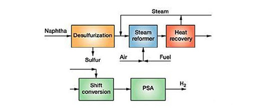
When naphtha is used, mixing it with recycled H2 at 42 bar vaporizes it. The mixture is preheated to approximately 380°C and hydrotreated on a cobalt-molybdenum (Co-Mo) catalyst bed in a reactor. Sulfur compounds are converted into hydrogen sulfide (H2S), which is adsorbed on a zinc oxide (ZnO) bed in another reactor before entering the reformer. Otherwise, the sulfur will poison the reforming catalyst.
The pressure drop across the catalyst bed should be kept low so that the flowrate ensures a complete reaction at process temperatures. The steam-to-carbon ratio is important and should be monitored. A suitable ratio must be maintained to avoid carbon deposition on the catalyst, or the reaction will not be complete. The ratio should be high (more than 2.5) to prevent deposition. This is achieved by mixing steam with desulfurized naphtha. Carbon formation on the catalyst blocks will increase the pressure drop over the catalyst bed.
Deposits inside the catalyst blocks affect the mechanical strength and activity. The high ratio helps to maintain and reduce the methane slip, decreasing methane in the reformed gas. The steam-to-H2 ratio is important, as well. The steam ratio should be around 20 for naphtha and 70 for natural gas. Reformer effluent is cooled by a waste heat recovery system, generating reaction steam and some byproduct steam. This is further passed to the shift reactor (shift converter), where CO is converted to CO2 and yields more H2: CO + HO = CO + H H produced in the reformer and shift reactor are mixed with other gases and must be purified.
In the case of ammonia synthesis, the H2 produced can be used as is, but secondary processing and treatment in refineries necessitate further purification. H2-rich gases are fed to the pressure swing adsorption (PSA) system, impurities are adsorbed on the Ni-based catalyst beds and purified H2 is collected (FIG. 1). To produce 38,000 metric tons per year (tpy) of H2, around 150,000 metric tpy of refined naphtha is used. Naphtha is converted to vapor before it enters the unit. H2 produced in the reformer and shift reactor is mixed with other gases and must be purified.
Design of the steam reformer. The reformer furnace is a critical and major component. It is called the primary reformer and is tubular in type. Cylindrical furnaces were used in earlier ammonia synthesis plants. The design has been recently optimized, and the reformer is a rectangular prism. Catalyst tubes are arranged in suspended form in a rectangular box with an outlet manifold system beneath the furnace.
The feed header is at the top, and flexible tubes connect the catalyst tubes. Burners are either at the bottom, sides or top. Catalyst tubes are connected to the outlet manifold, directly to an outlet or hot header, and then to a cold header. For onstream reliability, the design of packed catalyst tubes is critical and costs nearly half the price of the steam reformer.
Rectangular reformers are predominant and are of two types: multiple chambers with burners in the sidewalls of the furnace boxes, and a single furnace box with burners at the top. The type depends on the licensor and chosen design. Side-fired furnaces require more space than top-fired furnaces for the same heat duties. The first type is used for small duties and capacities, and flue gases exit at the top, making construction simple. The feed header is at the top, connected by flexible tubes to the catalyst tubes. Burners are either at the bottom, sides or top. The second is used for large duties and capacities; the high-heat flux design keeps the furnace size small.
Springs or a pulley/counterweight system support catalyst tubes at the top. At the bottom, they are connected to an outlet manifold, which directly connects to a cooler. The manifold consists of a hot header in the chamber connected to a cold collector outside the furnace.
In other cases, the catalyst tubes are attached through pigtails to a cold header. Such pigtails can be pinched when required to isolate the defective tubes and are helpful in the isolation of unwanted tubes without affecting the working cycle.
The total vertical expansion of the tubes must be accommodated by flexibility at the top (inlet piping) and outlet end. This is achieved by allowing freedom of linear movement, rotation at the top and linear rotation at the bottom. In alternative designs, only rotation at the bottom is allowed, but the top remains the same.
The tube size is based on process (flow, temperature and pressure) and economic considerations. Generally, the tubes used are 6 in. in diameter, and the heat transfer of the reaction governs the wall thickness. Heat transfer is affected at a metal temperature of 860°C−950°C. However, process temperatures may vary from 500°C at the arch level to 800°C at the furnace bottom at 43 bar.
Furnace. Each process licensor has optimized furnace designs based on feedback collected from various plant operations—experiments conducted, heat flux calculations (modified by experience for fixing process design kinetics and parameters), specifications, degree of reaction, space velocity, catalyst activity, degree of conversion, operating levels, endothermic heat requirements and heat flux.
Reformer furnace design requires great care. A detailed analysis of furnace type, heat flux variations, temperature gradients, firing type and tube arrangements are done to achieve optimum design. Once these and the process parameters are established (depending on the reaction kinetics and the mechanization of the functions and operations), the mechanical design is completed.
Temperature profile. The temperature profile governs the reaction completion, effectiveness and maintenance of tube skin temperatures; the tube portion within the reformer furnace, up to the header, must be monitored (FIGS. 2 and 3).
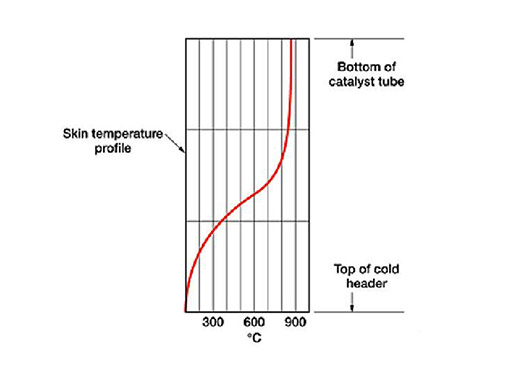
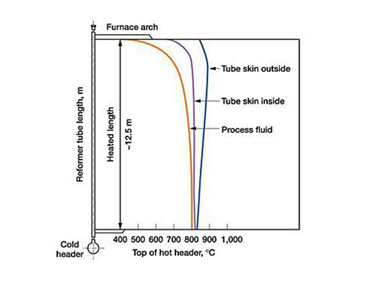
The temperature profile governs the flexibility analysis. This is done by providing free movement to tubes and containing stress within permissible limits. The stress is caused by furnace heat and provides flexibility and cold pull to allow expansion during furnace heating.
Burners. The fuel chosen (natural gas or naphtha) will govern the burner design. This depends on proprietary technology and the manufacturer’s design—the size of the flame and its envelope must be defined and chosen based on experience and judgment. The burners provide heat evenly and are transferred to the gases inside the tubes by radiation/convection. Using proven burners based on similar services is preferred to avoid future problems. The burner tips must be properly sized for the steam and naphtha to mix well inside the venturi and burn outside it.
The furnace is provided with a waste heat recovery system to conserve energy. The recovered heat is used to preheat the feed, combustion air and generate steam.
Tubes. Heat transfer in the reformer is about 40,000 British thermal units (Btu)/hr/ft−50,000 Btu/hr/ft at around 1,000°C. Exotic tube materials are required to withstand high temperatures and pressures in a highly corrosive environment. Tubes are cast out of HK-40 (high-temperature alloy steel) material [25% chromium (Cr), 20% Ni]. This material has superior resistance to rupture and deterioration at high furnace temperatures. Based on tube failure feedback, many manufacturers now use refined materials. A material better than HK-40 is 519 [24% Cr, 24% Ni, 5% niobium (Nb) and iron (Fe)].
Additionally, 35% Cr and 25% Ni materials with tungsten (W) are used because they can withstand high rupture and have better creep properties than low-alloy materials. Controlled burner firing, regulated methane and the prevention of tube temperatures from exceeding allowed limits help prolong tube life. This is achievable by efficient and experienced technicians and operators inspecting the tubes constantly during operations.
Important considerations for startup commissioning and operations. Steam reformer furnaces must be operated by experienced personnel. Care in maintaining uniform operating parameters and uniform heat emissions from burners are required. Operators should have sufficient experience to trim the burners with valves to attain the designed fuel-to-air ratio supply—uniform flowrates and heating must be maintained. Heat transfer is mainly done by radiation, but an appropriate hydraulic design must establish a uniform vertical gas flow on the flue gas side. This is achieved by providing ports in the side walls of the tunnels—the number of ports varies with the length of the tunnel. Closing or opening some of the ports enables final trimming. High skin temperatures also result from high-pressure drops across catalyst beds.
To exercise the required control, skin temperatures are monitored with pyrometers. A uniform temperature must be achieved in the furnace and tubes so that permissible skin temperatures are not exceeded. High temperatures, as per design, are to be maintained. At low pressures, the mass flow velocities are reduced, leading to tube red hotness. This causes high skin temperatures, shortening tube life. Important factors to consider are catalyst tube failure, burner performance, catalyst poisoning/choking, steam ratios, catalyst loading/unloading, frequent shutdowns, assessment of methane threshold limit and penthouse temperature.
Control system. Adaptive controls help achieve configurations and control all plant components, including digitally distributed control systems. Controlling feed and fuel systems are essential, as the feed system maintains the correct steam-to-carbon ratio. The fuel system ensures that various fuels are burned at the desired time with the correct quantity of combustion air, maintaining a constant exit temperature.
With the advancements in instrumentation controls, furnace control requirements may be able to integrate with instrumentation controls to make overall plant control possible without interruptions. Even the tube performance may be controlled by instruments.
PSA system. A PSA system includes adsorbers, purge vessels and a valve-control skid. PSA vessels use molecular sieves and a Ni-based catalyst. The catalyst adsorbs gases other than H2 in the synthetic gas going to these vessels. Regeneration of adsorbers is done with purge gas that sweeps through the PSA vessels and is collected in a buffer vessel. PSA operation follows a sequence of cycles including various steps controlled by a pressure-time diagram. Each PSA vessel comes in sequence in a set pattern generated and controlled by pressure sensing. Controls provided manage the depressurization steps, pressurization with the product and tail gas control.
Construction. The entire plant can be configured into manageable modules. This is done for transportation and construction to achieve quality and speed. Each module must be complete in its component form, with all mountings properly sequenced to fit into the adjacent one. Implementation schedules must be construction driven, and all measures to achieve quality must be fully accepted and followed across the organizational setup. The product is hazardous, and the flame is invisible. Welding, fabrication, erection tolerances and non-destructive testing requirements must be fully enforced to avoid mishaps during commissioning and operation.
Stabilized plant. The plant is simple in configuration; however, the PSA unit’s steam reformer control and methane threshold limit are the most important for stabilized plant operation. The care of the critical parameters and design features during implementation will help with the mechanical completion of a safe plant.
Takeaway. Various processes have been discussed with an emphasis on the most predominant (steam reforming of hydrocarbons)—technology is more evolved and accepted with the desired purity and production scale and vast acceptability, enabling its integration into industry. Methanol reforming technology is gaining use, and many well-known companies are standardizing their processes. Soon, the rising demand for H2 may be satisfied with this technology.H2T
About the author

VIJAY KHANNA has 26 yr of experience in the oil and gas sector while working with Engineers India Limited (EIL) until March 2001 out of 50 yr in engineering projects. He worked for Engineering Review of the Jumbo LPG I plant for Sonatrach in Algeria, was the project engineer manager for the first hydrocracker plant in India, and was the project manager for a grassroots refinery at Numaligarh, BPCL refinery expansion at Mumbai and several revamps. Khanna has published four articles on structural engineering, an article on H2 generation in Hydrocarbon Processing in 2001, reviewing maintenance essentials in the World Refining Journal in 2002, hydrocracker projects and the Numaligarh refinery project implementation in the EIL Journal. Khanna earned a B. Eng degree and a PGD in management.
Related Articles
Connect with H2Tech
