Articles
A finite element method analysis revealing the structural behavior of load bearing brackets
Maintenance and Reliability
A. KITTUR, Saudi Aramco, Ras Tanura, Saudi Arabia
The hydrogen (H2) generation unit (HGU) manufactures H2 by steam reforming propane and butane. In the final part of the HGU, the high-temperature shift conversion (HTSC) process takes place in HTSC reactors. A schematic flow has been illustrated in FIG. 1.
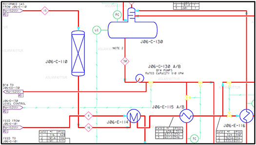
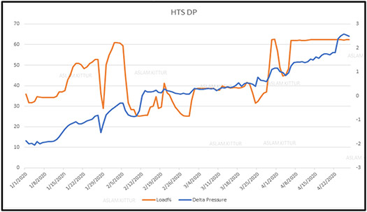
The shift conversion combines carbon monoxide (CO) with excess steam to produce carbon dioxide (CO2). More H2 and HTSC reduces the CO level in the reformed gas. In the reactor vessels discussed here, the gas and steam flow over an iron and chromium catalyst with a design life of 4 yr. Plant operators had observed an increase in the pressure drop trend for this reactor when the H2 plant was operating the steam reformer at approximately 63% load. The pressure drop (ΔP) was approximately 1.3 psi, showing a subtle rising trend, as shown in FIG. 2. However, in anticipation of achieving full production rates, the plant operations team was unsure of the maximum ΔP that could be tolerated by these HTSC reactor vessels in the event of full production rates.
Problem statement. The original equipment manufacturer’s (OEM’s) mechanical drawings of the HTSC reactors identified that only the dead weight (structural loads + catalyst load) had been considered for the strength of the internal ring, which is required to bear the overall load. The OEM’s calculations did not consider the operating fluid loads and the associated additional load due to the pressure drop across the vessel internals. The exact strength of the vessel internals—based on the maximum allowable ΔP—was unknown. Based on the available mechanical, process and instrumentation data, the steady rise of the ΔP across the reactor vessels would have a detrimental effect on the integrity of the internal structural grid that supports the catalyst bed. The maximum allowable ΔP across the operating HTSC reactor vessels is governed by the structural strength of the reactor’s internal grid. Mechanical calculations and additional finite element analysis (FEA)-based stress simulations were required to establish the ultimate strength of the HTSC reactor vessel internals corresponding to the maximum allowable ΔP across it.
ANALYSIS METHODOLOGY
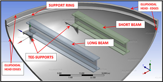
Finite element method (FEM) solid model. The reactor was modeled as a 90° 3D solid model based on the cyclical symmetry shown in FIG. 3. This model enables accommodating the geometric details for applying the appropriate loads and boundary conditions (i.e., only 25% of the vessel was modeled). Symmetric boundary conditions were applied to the model cut faces.
In terms of the dimensions, two cases were constructed and analyzed. The dimensions in the first case refer to the ΔP being based on a fully corroded thickness of the vessel’s internal structure since the reactor vessel had already witnessed more than 20 yr in service. The corrosion allowance is 0.125 in. on structures and 0.063 in. on vessel walls. These dimensions are referred to as MODEL-1: Hot & Corroded. Based on the most recent shutdown inspection results, the last recorded thickness of the ellipsoidal head revealed negligible corrosion for the previous 20+ yr of operating the HTSC reactors. Based on these results, a second model was developed for the analysis. The dimensions in the second case referred to the ΔP being based on an uncorroded thickness of the vessel’s internal structure due to the reactor vessel’s higher recorded thickness on the ellipsoidal head. These dimensions are referred to as MODEL-2: Hot & Uncorroded.
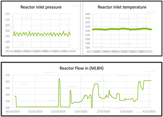
Internal loads. The catalyst weight, support beams and grids weight, operating liquid static head, velocity head, ΔP, mechanical loading and temperature distribution, as shown in FIG. 4, were accounted for while establishing the mechanical strength of the shell integral support structure.
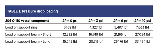
The tabulated summary in TABLE 1 depicts the calculated loads based on the multiple scenarios of pressure drop across the reactor vessel.
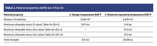
Material properties. The material specifications are SA 387 Gr-11 Cl-2, as shown in TABLE 2.1 The OEM has utilized the modulus of elasticity at design temperature (28.05E + 06 psi = 845°F). Alternatively, the modulus of elasticity at maximum operating temperature can be selected rather than the design temperature. This is because the temperature trends were known for the plant HTSC reactor vessel, which has never exceeded 630°ׄF, including any process upsets. The OEM utilized yield strength at a design temperature of 845°F (31,600 psi). Similarly, the yield strength at the maximum operating temperature can be selected rather than the design temperature.
The four basic stress intensity limits were satisfied as follows:
- The allowable value of Pm produced by internal design pressure and other specified mechanical loads, excluding all secondary and peak stresses, shall be less than Sm.
- The allowable value of PL produced by internal design pressure and other specified mechanical loads, excluding all secondary and peak stresses, shall be less than 1.5Sm.
- The allowable value of PL + Pb produced by design pressure and other specified mechanical loads, but excluding all secondary and peak stresses, shall be less than 1.5kSm.
- The allowable value of PL + Pb + Q produced by design pressure and other specified mechanical loads, but excluding all secondary and peak stresses, shall be less 3.0kSm.
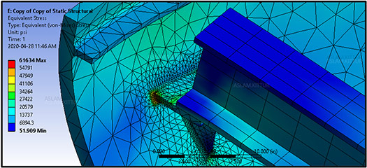
Results of the elastic stress analysis. An FEA based on linear, structural and elastic stress analysis was completed using ANSYS2 code. The reactor’s internal structural components were evaluated primarily for protection against plastic collapse. Although the operating pressure and temperature of the reactors were steady, the ratcheting and fatigue failure modes were not considered due to the infrequent nature of unit startup and shutdown cycles. An FEM with continuum elements provided the total stress distribution for evaluation, and the simulated stresses were compared with stress limits that are defined in ASME Section VIII Division 2,3 as shown in FIG. 5. This established the maximum load-bearing capacity of the structure and, consequently, the maximum allowable pressure drop that the reactor can safely sustain.
A ΔP 6-psi limit was established based solely on a fully corroded thickness of the vessel’s internal structure because the reactor vessel has already witnessed more than 20 yr of service. When the model geometrical dimensions were changed based on the last recorded thickness of the ellipsoidal head (18 yr), a ΔP of 10-psi limit was established. The interesting aspect of the stress simulation results established that the corner welds of the T-bracket that were welded to the internal ellipsoidal surface of the head always remained overstressed regardless of the increase in the operating fluid loads and the associated additional load due to ΔP across the vessel internals. This was especially true for the lowest weld on the vertical plate of the T-bracket assembly.
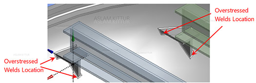
Takeaway. Based on the stress analysis results, the lowest weld on the vertical plate of the T-bracket assembly was found to be normally overstressed, as shown in FIG. 6. The equipment inspection records were verified from the past internal inspections completed during the plant shutdown. This location’s minor weld cracks were observed and repaired. Although this conclusion was not the objective of this analysis, it clearly explained the presence of minor indications on the weld, as noted in the inspection unit’s reports that followed the plant shutdown internal inspections.
An interesting structural behavior of this characteristic weld between the ellipsoidal surface and planar bracket creates an undesirable stress riser. The magnitude of the induced stress at this location was found to have a relation with the applied loads in the following manner:
- The magnitude of this induced stress did not exceed the allowable stress limit simply based on the applied dead weight loading (structural loads + catalyst load). The operating fluid dynamic loads and the additional associated load did not exceed the stress limit due to ΔP across the vessel internals.
- The magnitude of this induced stress was found to exceed the allowable stress limit, particularly based on the applied internal pressure of the reactor vessel. This behavior was observed even at a normal operating pressure level.
The above peculiar stress behavior was mainly due to the hoop/radial deformation of the ellipsoidal head in the outward direction due to the internal pressure, inducing a local primary stress beyond its acceptable limits. One way this feature could be avoided in future designs would be to design the T-brackets to be welded on the internal cylindrical surface of the shell instead of the ellipsoidal surface. This would have required major modifications to the reactor vessel and was deemed infeasible at this stage. For the continued mechanical integrity of the reactor vessel, a more rigorous inspection schedule and advanced techniques were adopted for future operations to address and mitigate the anticipated surface flaws in this characteristic weld geometry.
LITERATURE CITED
1 ASME Boiler and Pressure Vessel Code ASME Sec-II, Material Properties
2 ANSYS Theory & Application Guide.
3 ASME Boiler and Pressure Vessel Code ASME Sec-VIII, Pressure Vessels.
ABOUT THE AUTHOR

ASLAM KITTUR is a mechanical engineer with expertise in troubleshooting integrity issues related to refinery static equipment. Kittur is the Static Equipment Engineer for the Technical Services Division of Saudi Aramco, and has more than 23 yr of experience in the energy industry (upstream, offshore and downstream), specializing in performing stress analysis to understand the complex failure mechanisms of critical equipment. He focuses on establishing root causes for repetitive failures and developing solutions to ensure a reliable design for all operating conditions. Kittur earned an MS degree in solid mechanics and employs FEM-based structural and thermal simulations often required for a Level-III API-579 Fitness-For-Service Evaluation. Before joining Saudi Aramco, he served in a similar role in Canadian oil sands facilities for 10 yr.
Related Articles
Connect with H2Tech
