Articles
Optimize self-generated green H2 consumption via fuel cells and natural gas blending
Blending Natural Gas and H2
S. HARRIS, Emerson, Boulder, Colorado; and B. BURKOWSKY, Caltrol, Irvine, California
The Hydrogen Innovation Experience (FIG. 1) demonstration project created by Southern California Gas (SoCalGas) is drawing much attention as it provides a glimpse into one critical channel of the hydrogen (H2)-based energy distribution evolution. It illustrates how green H2 can be generated on a small scale using solar power combined with an electrolyzer. This H2 can be stored and eventually fed to a fuel cell, or it can be blended with utility-supplied natural gas. This reduces the carbon intensity of conventional natural gas-fueled appliances, particularly in legacy environments.
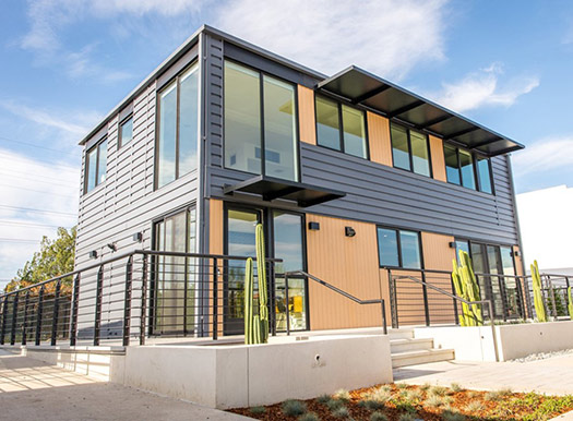
This project serves a single residence, but future plans include scale-up for use in existing multiple home neighborhoods, condo complexes, apartment buildings or commercial sites. Nonetheless, even on a small scale, the project identified some operational challenges and solutions.
Home appliances can use H2. SoCalGas has performed extensive experiments on the practicality of running conventional natural gas appliances (hot water heaters, clothes dryers, kitchen ranges, etc.) at a wide range of H2 and natural gas blends, and it has concluded that a H2 blend as high as 20% can work with unmodified appliances in most cases, while providing a significant reduction in overall carbon intensity. This determination then prompted the next challenge: How to mix H2 into the natural gas flow on a scale required for this project, with applicability for scale-up.
Residential natural gas consumption follows common daily cycles. It is lowest around 2:00 a.m. and then climbs steadily to its highest point around 7:00 a.m., coinciding with hot water use for morning showers. It falls in the afternoon, and then climbs to a second peak around 7:00 p.m., driven by cooking and clothes drying. This is logical in light of typical household activity, but it provides a major challenge since the volume can be anywhere from near zero to maximum, multiple times each day.
The control system injecting H2 into the natural gas stream must move in parallel with the natural gas flow; however, this is only 20% (at most) of the larger natural gas volume. It must also respond to major changes in flow, such as the starting or stopping of a large appliance. Design and construction of the control system was a JV between two of the author’s company’s partners: Caltrol was selected to design and build the control system hardware, working with Spartan Controls’ team of engineers. The successful implementation had to solve several important challenges.
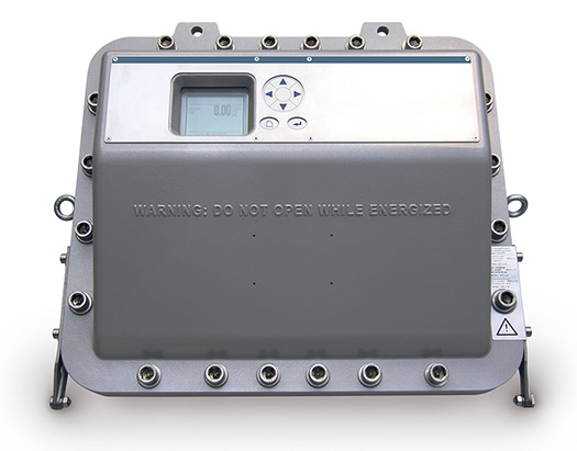
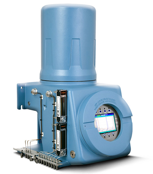
First, natural gas and H2 do not mix naturally due to their density differences; however, passing the blend through a static mixer homogenizes it long enough to reach the consumption point. Secondly, an analyzer is necessary to measure overall gas composition after H2 injection to verify that the blend is in spec. Two of the author’s company’s technologies can be used for this purpose: a thermal conductivity gas analyzera (FIG. 2) or a gas chromatograph (GC)b (FIG. 3). These have subtle differences of capabilities, but for small installations, the former is typically less costly and easier to operate.
Third, total gas flow can change suddenly and abruptly. At any given time, the project home can consume as little as zero gas, all the way to 400 ft3/hr (400,000 Btu/hr) if several major appliances are operating simultaneously (TABLE 1).
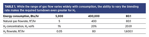
As a practical matter, the low end of the range has a base of 5 ft3/hr, so the total flow turndown range is 80:1. That is a wide range for any flowmeter—for the H2 side, it gets worse. SoCalGas needed to vary the H2 blend rate to as low as 1% for test purposes, although much of the time it operates at the maximum of 20%. As TABLE 1 shows, the H2 flowrate can range from 0.05 ft3/hr–80 ft3/hr depending on the total flow and blending proportion, resulting in a 1,600:1 turndown range for the H2 side.
Controlling the blend proportions. The initial control concept called for a flowmeter and control valve on both the H2 and natural gas lines (FIG. 4). The controller would monitor natural gas flow based on consumption and inject the specified percentage of H2 just ahead of the static mixer. An analyzer would then verify the blend before sending it to the appliances.
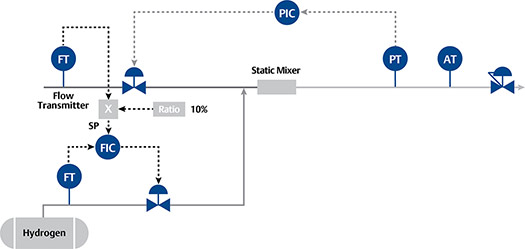
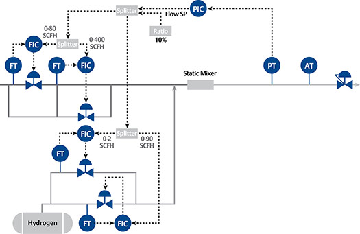
The author’s company’s product experts, consulting with the controller design team, recognized that with the required high turndown ratios, single flowmeters and control valves could not measure or control the flow on both sides with the desired accuracy across the entire range. The answer applies a common strategy for such situations: split control. Both supply sides must be split into high- and low-flow loops, each with appropriately sized components and effective control strategies.
The control system, as actually implemented (FIG. 5), is more complex. Both supply lines are split into two parallel sections, with large and small control valves and flowmeters.
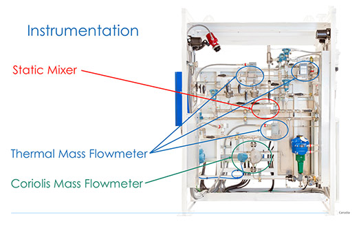
For all flow measurements (FIG. 6), mass flowmeters were chosen based on their specific capabilities related to gas applications. The high-flow natural gas measurement uses the author’s company’s Coriolis flowmeterc. However, the low-flow natural gas and H2 measurements called for proprietary thermal mass flowmetersd to handle the reduced flows. Another company’s control valves and regulators round out the component liste.
These all feed to the controller within the automation systemf, which reads the process variables, makes the necessary calculations and adjusts various valves to ensure a desired mixture, confirmed by the analyzer. The entire systems must adjust quickly to load changes, even if they can be unpredictable and abrupt, as in this application.
Operational details. The main photovoltaic array on the carport produces six kilowatts (kW) during peak times, plus supplemental power from panels on the house roof. All power generated by the arrays is channeled to the battery system, which can store a maximum of 300 kilowatt hours (kWh), and it is distributed from there.
The electrolyzer is a small unit, capable of delivering 1 kilogram (kg) of H2/hr. It consumes most of the power generated by the arrays, so it is only used at peak times. The electrolyzer delivers H2 at a pressure of 30 bar–32 bar (435 psi–465 psi), which is fed to the storage tank without additional compression.
The storage tank holds approximately 10 kg of H2 at that pressure, and it can be fed to the fuel cell or blending skid, as desired. The fuel cell consumes about 70 g of H2 to produce 4 kWh of power to the home.
The blending skid can mix in whatever proportion the operators request at a pressure of 1.7 bar (25 psi). It sends the blended gas to a conventional gas meter, where pressure is reduced to normal residential level for distribution to the home’s appliances. When the H2 proportion is 20% or less, there is no effect on the performance of any appliances, just a reduction in emissions.
Scaling up. Moving from a single residence to a more practical and economical scale with multiple residences—and perhaps small commercial properties—that share common infrastructure calls for additional considerations. The same concepts learned from the Hydrogen Innovation Experience apply, but some are more nuanced.
The Hydrogen Innovation Experience set out to be fully self-sufficient for electrical generation, taking nothing from the grid, although water and natural gas connections were used. A larger project would have to determine if such self-sufficiency is required.
If power can be drawn from the grid when necessary, this provides a wider range of options for internal power distribution, including required battery system capacity and the amount of power available for generating H2. Additionally, conditions will determine how much H2 is blended with natural gas vs. fed to the fuel cell to create electricity.
When increasing gas blending capacity to service multiple properties, the functional role is much like a larger pipeline-installed blending facility. Consequently, a variety of other considerations come into play—the blending station must:
- Measure the pipeline flow and pressure feeding the cluster of users, and it must also capture samples of incoming natural gas for analysis to determine what level of H2 may already be present from other blending installations upstream.
- Have compressor capacity to match the pipeline pressure.
- Have a second analyzer far enough downstream from the injection point to allow for complete mixing and verification that the H2/natural gas blend is within spec.
When this functional concept is applied at a large enough scale to be commercially practical, economic considerations will be balanced with sustainability. The decision to divert power to an electrolyzer, and the choices of how to use the resulting H2, will be different in each situation. However, the experiences and data collected from demonstration projects will provide a critical base for all evaluations.
This demonstration project brings the operational possibilities to life and provides a roadmap for scale-up. It paves the way for future consumption of solar power and natural gas in a sustainable manner through the use of clean H2, both for power generation and storage via fuel cells, and blending with natural gas for use in home appliances.H2T
NOTES
a Emerson’s Rosemount™ X-STREAM XEFD Continuous Gas Analyzer
b Emerson’s Rosemount 700XA Gas Chromatograph
c Emerson’s Micro Motion Coriolis flowmeter
d Brooks thermal mass flowmeters
e SpartanPRO™ H2 blending solution
f Emerson’s DeltaV™ automated control system
About the authors

SETH HARRIS is the Director of Sustainability Sales in the Americas for Emerson. His more than 17 yr of experience with Emerson across multiple industries, various sales functions including product, software and data management, and a personal foundation built on environmental sustainability bring a unique depth to society’s decarbonization efforts. He holds a BS degree in chemical engineering from the University of Colorado.

BRIAN BURKOWSKY is the General Manager of Advanced Solutions at Caltrol, an Emerson Impact Partner. He works with the Advanced Solutions group to apply its extensive industry solutions capabilities—including IP-centric applications, integrated solutions, engineering and manufacturing capabilities for process industries—to solve customer problems. Burkowsky holds a degree in instrumentation technology from the Saskatchewan Polytechnic Institute.
Related Articles
Connect with H2Tech
