Articles
H2 purification: Take on new challenges by leveraging existing solutions
Process/Project Optimization
F-X. CHIRON, Axens, Paris, France
Green, blue, pink, yellow or white: regardless of its color, low-carbon hydrogen (H2) will play a significant role in the energy transition and the future of transportation. Decreasing the capital expenditure (CAPEX) and operational expenditure (OPEX) of clean H2 production remains challenging. Electrolyzer manufacturers are building giga-factories to decrease the cost of stacks, but traditional H2 players tend to rely on carbon capture in huge-scale H2 plants. Not only is there pressure to produce cost-competitive, low-carbon H2 at scale, but new applications also call for ultra-pure H2.
Purification is often seen as a black box that, no matter what, must deliver up to 99.999 vol% H2. H2 coming out of a manufacturing process [e.g., methane (CH4) reforming, electrolysis or stored geologically] comes together with an array of impurities such as oxygen (O2), water, carbon oxides or sulfur. However, the use of H2 in mobility via a fuel cell or as a reactant in a catalytic conversion imposes tight specifications, especially on O2 and water.
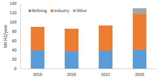
Refineries use about 40 MMtpy of H2 that is mainly produced by naphtha crackers, steam methane reformers (SMRs) and catalytic naphtha reformers [continuous catalytic reforming (CCR) or semi-reg]. H2 is used mainly for hydrodesulfurization and hydrocracking reactions. The general manufacturing industry is the other big H2 consumer, especially in producing ammonia (fertilizers), methanol (to produce other chemicals) and the direct reduction of ore within steel mills. Industrial consumption of H2, excluding refineries, is about 50 MMtpy and is forecast to reach more than 75 MMtpy in 2030, as depicted in FIG. 1. New applications, such as H2 for transportation, are also forecast to become significant from 2030 and beyond.
For decades, H2 purification techniques have been employed in the oil refining and synthetic gas (syngas) industries. Catalysts and adsorbents have been developed by catalyst manufacturers and improved over the years so that H2 plants can run continuously and safely. The H2 purity level depends on the downstream processes.
Over the last couple of years, H2 has been heralded as one of the most promising vectors to help decarbonize industry and transport. H2 reacts with O2 across an electrochemical cell like a battery, producing electricity, water and small amounts of heat. Fuel cells are sensitive to impurities, and only ultra-pure H2 can be utilized.
The upcoming challenges regarding H2 purification are not related to technology, but rather on the ability to deliver products (adsorbents and catalysts) at scale with technical know-how while being able to engage in providing performance guarantees.
This article focuses on H2 purification techniques and highlights how the catalyst and adsorbent industry is ready to answer future needs. Commercially proven catalysts and adsorbents can be readily used in most applications where H2 must be purified.
There are as many impurities as there are ways to produce H2. The nature of H2 impurities will depend on its manufacturing process or storage. Today, only a few production processes are commercially available at scale, and this article will focus on proven H2 manufacturing technologies. This includes the following:
- Steam reforming (mainly of CH4)
- Catalytic naphtha reforming
- Gasification of coal
- Water electrolysis.
Besides water electrolysis, where only a final purification is needed, the other techniques require several further conversions, such as a catalytic water gas shift, an acid gas removal unit (AGRU) or pressure swing adsorption (PSA). These techniques are well described in literature and provide satisfactory H2 purity for many cases, such as ammonia or methanol production processes.
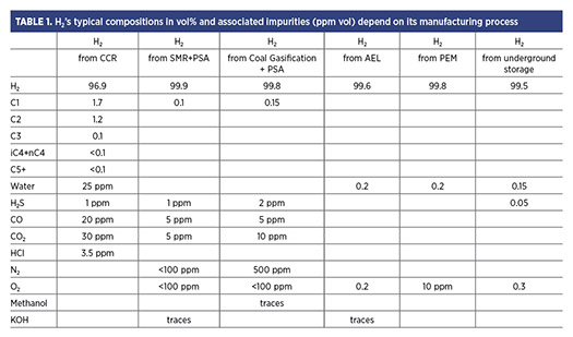
When H2 is used in a more sensitive application, such as catalytic hydrogenation of chemicals or direct use in a fuel cell, trace impurities must be carefully examined and addressed so downstream operations can run efficiently. TABLE 1 summarizes H2 purity from different manufacturing processes, focusing on trace impurities. Another concern regarding H2 impurities is storage; only underground storage can answer the need for massive storage. However, one issue with underground storage is that even if ultra-pure H2 is injected, impurities coming from the storage will be found in H2 at the time of withdrawal. TABLE 1 also presents the impurities found in H2 geologically stored in a salt cavern.
FROM REFINERY H2 TO FUEL CELL H2
Refining, ammonia and other chemical production facilities use H2 to dictate necessary purification levels. This is why dedicated purification sections based on adsorbents and catalysts have been developed to protect downstream processes in all chemical, fertilizer and refining sectors.
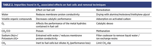
The ISO-14687-2019 norm dictates tight specifications on H2 quality so that it can be used in fuel cells to create electricity. Several technologies exist, such as molten carbonate, alkaline, solid oxide or proton exchange membrane fuel cells (PEMFCs). Fuel cells are essentially reverse electrolyzers where H2 and O2 react to form water and electricity. Therefore, materials used in fuel cells are the same as in electrolyzers, which makes them sensitive to contaminants. In the field of fuel cells, PEMFCs are dominant, and TABLE 2 lists the effects of contaminants.
Some applications require additional stringent specifications, such as H2, to be liquefied for transportation. There are no specifications yet, but common limits are 1 part per million (ppm) water and 1 ppm O2. Depending on whether the H2 is produced via SMR, water electrolysis or catalytic reformer, several impurities will be present, and the choice of processes and products to be used will depend on the subsequent use of the H2.
CATALYSTS AND ADSORBENTS USED IN H2 PURIFICATION
Catalysts and adsorbents are used for H2 bulk or fine purification, depending on the impurities on one side and the H2 purity needed on the other.
Adsorbents used in PSA and temperature swing adsorption (TSA). Adsorbents have been used in the oil and gas industry for decades, mainly for drying and sulfur removal in fixed beds. Adsorbents work by creating weak bonds between the impurity and the surface. As long as there are free active sites for the impurities to be retained, the bed is in adsorption mode. When the bed of adsorbent has reached its total capacity, regeneration must be done to desorb the impurities and make the adsorbent(s) ready for another round of adsorption.
Several adsorbents can be used alone or in combination. The most common are activated alumina, silica gel and molecular sieves—molecular sieves are the most used for purification and drying.
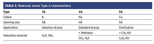
TABLE 3 shows that type A molecular sieves (3A/4A/5A) are crystalline metal alumino-silicates. They consist of a 3D zeolite structure made of silica and alumina that carries a net negative charge balanced by a cation, such as Na+. Within the zeolite structure, the cations are located over the pore opening, thus partially blocking the entrance to the zeolitic cage. Therefore, the cations determine the pore opening size, only allowing small enough molecules to enter the structure to be retained by the negative charge. This is why they are often referred to as molecular sieves.
Two main processes based on adsorbents are employed for H2 purification and discussed in the following sections: PSA and TSA.
PSA: Bulk separation of carbon oxides from H2. PSA technology is well known and commercialized to carry out H2 separation from carbon oxides—ammonia and classic H2 plants found in refineries employ this technique. In H2 PSA, the most common product combination is a layer of 5A molecular sieves and activated carbon, sometimes with the addition of an extra layer of activated alumina. The PSA process is based on physical adsorption, whereas highly volatile compounds with low polarity, as represented by H2 or helium, are practically non-absorbable compared to molecules such as carbon dioxide (CO2), carbon monoxide (CO), nitrogen (N2) and hydrocarbons. Most impurities in a H2-containing stream can be selectively adsorbed, and a high-purity H2 product is obtainable.
The drawback of a PSA system is that some H2 is lost due to the rapid cycling of the vessels. In new applications, this can even be prohibitive and prevent the PSA from being used downstream of electrolyzers.
TSA: Deep H2 drying. TSA is another technology employed in countless applications in the oil and gas industry. The prime application of TSA is drying, and the principle remains the same as for PSA—a polar molecule adsorbs onto the adsorbent leaving the non-polar molecules (H2) passing through the bed without being affected.
Fixed-bed vessels alternate between the adsorption phase at low-to-ambient temperature and reaeration or desorption at moderate-to-high temperature. Familiarity with regeneration is key to ensuring optimal and smooth operation throughout the bed lifetime (FIG. 2).
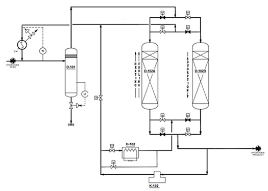
The molecular sieves selection depends on the type of impurities found in the feed and the expected outlet water concentration. For example, a 4A sieve will ensure a water concentration of 1 ppm mol and lower. Few options are possible to regenerate the adsorbent (using wet feed or recycled dry gas). FIG. 3. illustrates the layout of a TSA where part of the dry gas is used for regeneration. This regeneration gas is recycled to the unit inlet so that no H2 is lost.
Guard bed adsorbents. Guard beds are non-regenerable adsorbents with an intrinsic capacity to remove impurities, and a chemical reaction fixes the impurity onto the adsorbent. Due to this, the impurity cannot be desorbed and will stay on the adsorbent until it is unloaded. Regarding H2 purification, sulfur guards are mainly employed when there is a need to protect a catalyst or to reach on-spec H2 (export).
These materials are loaded in fixed-bed reactors and ensure that virtually no impurity breaks through the bed throughout the entire lifetime of the adsorbent. Outlet impurity levels can be observed as low as a few parts per billion (ppb). Guard bed vendors ensure that the bed design allows maximum pick-up capacity and consider mass transfer diffusion and intrinsic kinetics so that the whole volume of the adsorbent is used to maximize the bed’s lifetime and time between bed change-outs.
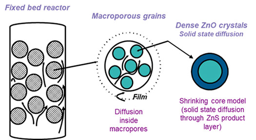
FIG. 4 illustrates how zinc oxide (ZnO) guard bed materials work for hydrogen sulfide (H2S) removal. H2S first diffuses from the bulk to the grains and inside the macropores. Then, H2S reacts with ZnO to form zinc sulfide (ZnS) and water. A shrinking core model accurately represents the kinetics of this gas-solid reaction. This considers that as the adsorbent is consumed, H2S must diffuse through ZnS to react with fresh ZnO.
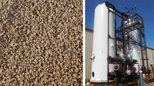
ZnO-based materials are efficient and display high pick-up capacity, but the kinetics of the reaction must be carried out at moderate temperatures (at least 150°C). New materials have been developed to react to H2S at ambient temperatures. These solid scavengers are based on mixed-metal oxides and can show up to 50 wt% sulfur capacity (FIG. 5).
CATALYSTS
Deoxo catalyst. Catalysts are employed in the H2 purification process to meet special requirements. For instance, if O2 is present in the H2 stream, a deoxo catalyst will ensure that all O2 is converted to water (Eq. 1):
H2 + ½ O2 = H2O (1)
This reaction is easy but necessitates using precious metals to lower the reaction temperature to almost ambient. Palladium (Pd) or platinum (Pt) -based catalysts are employed in deoxo systems to abate O2 from 5 ppm mol to as low as 1 ppm mol.
Deoxo catalysts are sensitive to amines, sulfur, CO and liquid water traces. It is usually recommended to operate a Pd-based deoxo catalyst a few degrees above the dew point. Catalyst vendors’ know-how in precious metal impregnation is essential, as Pd and Pt prices are extremely high.
Methanation catalyst. Methanation catalysts have been employed to remove traces of carbon oxides. For fuel cell applications, CH4 levels in H2 can be up to 100 ppm vol, whereas the maximum CO2 and CO levels are 2 ppm vol and 0.2 ppm mol, respectively. Carbon oxides are often considered catalyst poisons when CH4 is more inert. Due to this, converting traces of CO/CO2 into CH4 is usually recommended (Eqs. 2 and 3):
CO + 3 H2 = CH4 + H2O (2)
CO2 + 4 H2 = CH4 + 2 H2O (3)
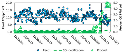
The reaction consumes H2 and produces water. This well-known exothermic reaction is catalyzed by nickel and usually carried out near 200°C that converts virtually all carbon oxides into CH4. The graph in FIG. 6 illustrates the performances of the author’s company’s methanation catalyst. The conversion is total until a breakthrough is observed. The breakthrough is due to chloride contamination, confirmed by post-mortem analyses of the catalyst. Nickel catalysts provide total conversion but are sensitive to many poisons, including sulfur, chloride or arsine. Dedicated guard beds are usually installed upstream of the catalyst to protect it.
APPLICATIONS
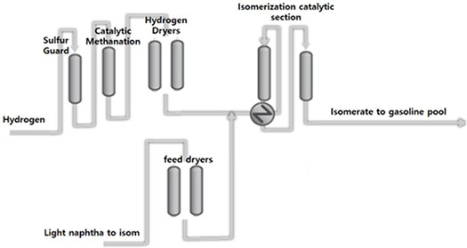
Protecting the isomerization catalyst by using a combination of adsorbents and catalyst. The isomerization process (used to increase the octane number of a fuel by converting normal paraffins to iso-paraffins) is a perfect example of how a combination of adsorbents and catalysts have been employed to purify H2. In this process, H2 is fed with naphtha over a Pt-based catalyst. This catalyst is sensitive to CO/CO2 and moisture. The H2 required comes from an adjacent CCR or a local SMR, each with their own impurities (chloride, sulfur, CO, CO2 and/or water). The following H2 purification scheme is recommended so the isomerization catalyst can reach a much higher lifetime than when H2 is fed directly to the system. FIG. 7 illustrates the H2 purification steps, comprising a ZnO guard that removes H2S and potentially traces of hydrochloric acid—a catalytic methanator that converts traces of CO/CO2 into CH4, and a set of driers loaded with 5A molecular sieves that dry and can also act as a last barrier against carbon oxides.
H2 purification downstream of an electrolyzer. Electrolyzers [alkaline (AEL) or proton exchange membrane (PEM)] produce very clean H2, as seen in TABLE 1. However, the tight specification of H2 used in fuel cells or sent to a cryogenic unit for liquefaction imposes further purification.
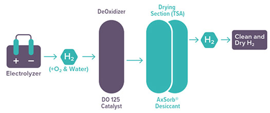
A purification and drying unit (PDU) is located directly downstream of an electrolyzer. This purification package includes a deoxo catalyst and molecular sieve driers in a zero-loss TSA system. Depending on the electrolysis technology (AEL/PEM), H2 comes out with different O2 levels but is always water saturated. O2 is easily reacted with H2; subsequently, the gas is cooled, and water is knocked out before entering the dehydration section (FIG. 8). H2 from the PDU is ultra-pure and can be certified with a maximum of 1-ppm vol O2 and 0.1-ppm vol water.
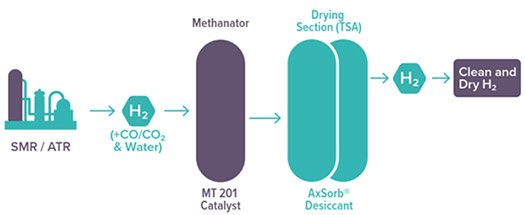
SMR fine purification. Similarly, a PDU can be utilized on blue H2 downstream of the PSA. This unit is like the PDU on electrolyzers; however, the difference is that traces of CO/CO2 must be removed rather than O2. Carbon oxides are well-known poisons to fuel cells and catalysts used in the hydrogenation of toluene for liquid organic H2 carrier (LOHC) applications. A pre-reduced methanation catalyst can effectively bring the CO/CO2 level to ultra-low concentrations. Methanation is classically followed by a zero-loss TSA system integrated on a skid (FIG. 9).a,b
Underground H2 purification. Manufactured salt caverns are one of the few ways to store large quantities of H2, and these formations can be several hundred meters deep and tens of meters in diameter. H2 can be stored at a pressure close to 200 bar. The brine at the bottom of the cavity and bacterial activity inside the cavern contaminates the H2 leaving, loading it with sulfur (typically 200 ppm mol H2S) and bringing it close to water saturation levels (FIG. 10).
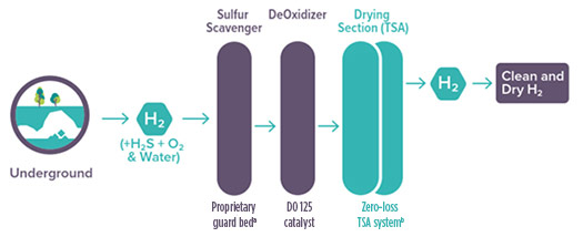
The operating conditions are well suited for sulfur scavengers that operate best in water-saturated conditions. If needed, a deoxo system can help to remove any O2 before entering the dehydration section.a H2 is classically dried with alumina or molecular sieves, but a TEG can advantageously be used if the water specification is not too tight (above 30 ppm mol).
Takeaways. H2 purification has been carried out for many years with a combination of catalysts and adsorbents specifically developed to protect downstream sensitive and/or expensive catalysts. Approximately 95% of H2 is used in refineries or in the chemical industry today, but future H2 applications necessitate a new level of purification. The recent development of using H2 in fuel cells for transportation as a liquid or via LOHC has created new ultra-purification challenges. Know-how in precious metal impregnation and adsorbent manufacturing is essential to purifying H2. Today, production facilities of 200 MW−500 MW are announced consistently (e.g., a 390-MW project has been announced in Ordos, China by Sinopec, corresponding to 40,000 m3hr–100,000 m3hr of H2 produced by AEL) and 1-GW (200,000-m3hr) projects are on the near horizon.1,2 Scaling-up H2 production means scaling up H2 purification, as well. Those mega projects will represent several tons of deoxo catalysts and tens of tons of desiccants installed per plant.H2T
LITERATURE CITED
1 Sinopec, “Sinopec launches the world's largest green hydrogen-coal chemical project in inner Mongolia,” February 2023, online: http://www.sinopecgroup.com/group/en/Sinopecnews/20230331/news_20230331_502557647316.shtml
2 Hydrogen Insights, “German developer unveils second gigawatt-scale green hydrogen project,” January 2023, online: https://www.hydrogeninsight.com/production/4gw-by-2030-german-developer-unveils-second-gigawatt-scale-green-hydrogen-project/2-1-1394224
NOTES
a AxTrap 4000
b AxSorb® Desiccant
About the author

FRANÇOIS-XAVIER CHIRON started his career at bp in England and later joined Topsoe in Denmark as a Technology Manager working on syngas conversion. In 2017, Dr. Chiron returned to France and joined Axens in the adsorbent department as a technologist. In 2023, he was appointed Business Development Manager in the Low Carbon and Gas Business Division in Axens. Dr. Chiron earned an MSc degree in chemical engineering from CPE Lyon, a PhD from the Ecole Polytechnique of Montreal and a business development degree from DTU Business School in Copenhagen. Dr. Chiron has co-authored eight articles and holds five patents.
Related Articles
Connect with H2Tech
