Articles
Design and utility of H2 recombiners
Safety and Sustainability
K. LATURKAR, Facility for Rare Isotope Beams, Lansing, Michigan; and K. LATURKAR, Validation Associates, Boston, Massachusetts
There have been several instances of commercial hydrogen (H2) recombiners being used in industrial and scientific facilities to handle the H2 produced inadvertently and unavoidably from radiolysis of water after activation.1,2 A high rate of H2 production may result from various kinds of reactions and other reaction parameters. An unchecked rate can produce a combustible mixture with the surrounding air and cause an uncontrolled explosion if it is accidentally ignited.
H2 management can be accomplished through various methods, either independently or in conjunction. Inert gases might be utilized for dilution, intentional and controlled ignition could be performed at concentrations less than the flammability limit, and H2 consumption devices could be used.3 One of the most prominent tools used to manage inert gases H2 recombiners, which involves the combination of H2 with oxygen over noble metals under controlled conditions. The high activity of noble metals such as platinum, palladium and rhodium make them ideal catalysts for recombination reactions.4
By using the H2 recombiner, low H2 content (below 2 mol%) can be maintained in the recirculating loop. To comply with safety standards, the H2 recombiner ensures that the lower flammability limit (4 mol%) is never exceeded, using analyzers at strategic locations.5 The reactor design varies in complexity, but oxygen is provided in controlled amounts to limit the excess H2. These devices allow the control of H2 concentration in the system, thus preventing the hazards associated with unintentionally produced H2.
H2 recombiners are available in different sizes and dimensions depending on the volume of H2 to be handled.6 Due to the different production rates of H2 and oxygen after radiolysis7 and the subsequent preference for absorption of oxygen in water,8 there is a difference in the concentration of gases reaching the reactor. Consequently, an oxygen line is added before the reactor's inlet to facilitate H2 and oxygen reactions. Oxygen concentrations for the reaction are made up by this supply of 100% pure oxygen when its concentrations are below the amount needed for complete recombination. The amount of oxygen supplied to the reactor depends on the complexity of the reactor design and the fact that the overall H2 concentration must be less than 2% at all recombiner locations. Therefore, the limiting agent in the reaction is oxygen, which is almost completely consumed while H2 is in excess. Both the oxygen control valve and the electric preheater ensure that the recombination reaction takes place at the right concentration and temperature, respectively.
There is a limit to how much H2 can be converted. Consequently, the outlet gas composition tends to consist mainly of unreacted H2, negligible amounts of oxygen, water vapor and any inert components present in the system. If the inlet stream composition, flowrate and operating parameters are properly selected, pressure drop across the catalyst bed will be minimized. Various factors affect the efficiency of the entire process, which can range from 80%–95%.9,10
Utilizing an inlet pressure regulator, the nitrogen feed to the recombiner system maintains pressure inside the loop. Nitrogen is introduced across the loop through a flowmeter if the pressure in the recombiner loop drops below its setting. If the loop pressure rises beyond the required value, the back pressure regulators on the gas-lined-steel (GLS) tank will close, venting excess pressure to the offgas system.
H2 RECOMBINER EQUIPMENT SETUP
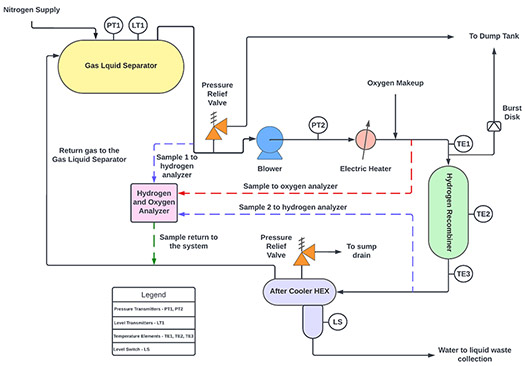
Based on the process, the location and the space requirement, the system can be spread out or incorporated into a compact skid. There are four main components of the system: a recombiner vessel, a blower, a preheater and an aftercooler. The system is equipped with instrumentation that includes flowmeters, temperature transmitters, pressure transmitters and gas analyzers (FIG. 1).
Blower. Recombiner skids use an electric hermetically sealed blower to circulate gases in a closed system. During operation, the blower takes gases from a gas/liquid separator (meant to remove entrained particles and droplets from gaseous processes), passes them through the recombiner and returns them back to the GLS tank. For specific process conditions, a single blower can provide 100% of the flowrate, although multiple blowers can be used in parallel depending on the requirements. To maintain the H2 concentration at less than 50% of the lower flammability limit (LFL), a variable frequency drive can be installed to control the blower speed and provide the required overall gas flowrate.
Pre-heater. An electric heater with a metal sheathing provides the essential amount of heat for a sustained flow of containment gases heated up to a temperature of at least 110°C. By increasing the activation energy of the constituent gases, the H2 recombiner catalyst bed can initiate the recombination reaction. An additional reason to raise the temperature above the boiling point of water is to prevent condensation in the catalyst bed, as all water at this temperature is transformed into vapor. This keeps the catalyst's activation sites from being blocked.
Recombiner vessel. A recombiner is a gas phase reactor containing a catalyst bed that catalyzes the reaction between H2 and oxygen in the circulation gas, which comes from the GLS tank. After being pre-heated, the gases pass through the recombiner and cross over the catalyst bed, which is heated to 500°C–700°C during recombination. An outer enclosure protects the recombiner from heat loss to the surroundings by acting as an insulation layer. At the inlet and outlet of the catalyst bed, detonation arrestors are provided inside the recombiner. A flame front will not propagate in the recombiner if abnormal operating conditions are present. In the reactor, flow occurs vertically down the catalyst bed. After recombination, gas leaves the bottom of the recombiner and flows into the aftercooler. The oxygen deficit mode allows the system to function so that essentially 100% of the oxygen in the system reacts. The oxygen control valve and preheater are responsible for maintaining the temperature and concentration required for the recombination reaction.
Catalyst. H2 recombiners use a variety of catalysts. Usually, these include coatings such as Pt or Pd over alumina substrates. Among the commercially available catalysts are the BASF R0-20/47 catalyst (particles with diameters ranging from 2 mm–4 mm, which contain 0.47 wt% Pd on an Al2O3 carrier);11 another is Research Catalysts Inc.'s OxiGone 130, composed of 0.3 wt% Pd on 2 mm–4 mm Al2O3 beads.12 Catalysts of this type have adequate porosity and large catalyst surfaces (90 m2/g –100 m2/g) of pellets, although the amount of active surface area participating in catalysis is only 5 m2/g. These catalysts can operate up to a temperature of 500°C–700°C, depending on the type of catalyst and process conditions.
Aftercooler. In the aftercooler, the process water flows through the exchanger shell, while the gas is cooled after the recombination flows through the tube side and the water vapor formed after the reaction is condensed. The aftercooler is equipped with a pipe sump that collects this condensate, signaling the presence of water through a level switch that is transferred to a waste tank for further processing.
Instrumentation. High-quality instrumentation is essential for a successful recombiner operation. As part of the recombiner system, several instruments provide information about system parameters, so that by measuring them, the operation can run more efficiently to give a more robust control in the system. The following is a list of instruments included in the system:
- Flowmeter. The flow of gas between the GLS tank and the recombiner is controlled by a control valve linked to a flow-indicating controller. The flow-indicating controller transmits a dynamic set point—based on the H2 concentration recorded by the analyzer—to the flow control valve located just before the blower. The valve then opens and closes according to this requirement. For all expected operations, this flow control makes it easy to keep the H2 concentration below the LFL.
- Pressure transmitters. An alarm signal is sent if high pressure is detected by the pressure transmitter in the blower discharge line, alerting the operator. Conversely, if the pressure transmitter detects low pressure, an alarm signal is sent to alert the operator to a low pressure in the blower discharge line. For both cases, the blower speed can be manipulated to restore normal operation.
- Temperature transmitters. Multiple temperature sensors are located across the recombiner skid. These temperature transmitters ensure that the system temperature is not too far outside the normal operating conditions at any given point, preventing potential hazards to the process.
By using a temperature transmitter downstream of the electric heater, the output of the heater element is automatically adjusted to meet the desired gas temperature. A signal alerts the operator to act if a high temperature is detected. An alarm will activate when the temperature continues to rise, forcing the electric heater to shut off. Alternatively, if a low temperature is detected, a signal is sent to the operator to check system performance, although no interlocks are necessary.
The recombiner consists of three temperature transmitters: at its entry, at its outlet and in the middle of the catalyst bed. Operators can monitor the temperatures of the recombiner through these temperature transmitters. If any of these temperature indicators indicate a high temperature, alarms are activated to warn the operator. As the temperature continues to rise, a signal is activated by a high temperature alarm and the interlock is triggered to shut down the heater and the blower.
To assist operators in determining if the aftercooler is functioning properly, a temperature indicator is placed in the gas return line leaving the aftercooler. In the event of a high temperature being detected, a signal is sent to the operator to increase the process water supply to the other side of the aftercooler to restore normal operation.
Level transmitters. In the event a high level is detected in the boot of the aftercooler by a level switch, an automatic control valve opens to direct the water from the sump to the waste handling system.
Analyzer. The concentration of H2 in the loop is monitored by a multiplexed H2 analyzer, and the flow is controlled by individual flow controllers. Recirculating cooling loops are equipped with these to ensure low H2 content (less than 2 mol%). Process control ensures that the lower flammability limit (4 mol%) at any point of the process is not exceeded. In a similar manner, an oxygen analyzer is provided to monitor the oxygen concentration in the recombiner feed gas. To ensure redundancy and better concentration recording, it is best to install more than one analyzer at different locations.
THEORY
The reactor design is based on parameters specific to a facility, but the basic principle is the chemical reaction that results from H2 reacting with oxygen and forming water. Activation energy must be overcome before the reaction can begin. Recombination happens between H2 and oxygen as per the reaction in Eqs. 1 and 2:10
H2+12O2→H2H2+12O2→H2 (1)
(∆H∘rHr° = -240 kJ/mol) (2)
In these reactions, the catalysts reduce the activation energy threshold significantly with the reaction initiated at low temperatures. When H2 molecule bonds are broken, radicals are generated that react quicker with free oxygen radicals.
The Langmuir-Hinshelwood mechanism governs the catalytic oxidation of H2 on metals.13 The reactants diffuse on the catalyst surface, and then those reactants absorbed on the catalyst surface react with each other.
When the gas enters the vessel and encounters the catalyst, the H2 and oxygen components are adsorbed into the solid catalyst particles, then recombined into the water by chemical decomposition. Then, under the influence of the heat of the chemical reaction, the gas releases from the absorbed state and leaves the catalyst surface in the form of water vapor.
Safety system and interlocks. NFPA standards apply to all electrical equipment and instrumentation. In this way, unwanted fires are prevented. An adequate number of active and passive safety interlocks have been incorporated into the system to ensure safe operation and thereby reduce the chance of an untoward emergency. Here is a list of the interlocks involved in the process:
- Blower failure. The variable frequency driven blower will shut off the electrical heater if a blower failure is caused by a power failure or mechanical failure, which is indicated by a low-low flow downstream of the blower.
- Detecting high/low outlet temperatures. If the electric heater outlet temperature rises significantly above the desired set point, the interlock shuts it down immediately. However, if a low temperature is detected in the heater downstream, the blower is turned off to prevent wet vapor from entering the recombiner, which can poison the catalyst.
- High constituent concentration. The recombiner includes a multiplex analyzer that measures H2 and oxygen concentration before and after the recombiner so that the optimal amounts enter the recombiner. This analyzer is directly connected to the blower speed, ensuring a concentration of H2 of no more than 2%. In the event of an increase in concentration of constituents beyond the set values, the interlock shuts down the heater and blower. Adding an inert gas, such as nitrogen, can dilute the H2 concentration in the system before restarting.
- High recombiner temperature. For an uncontrolled reaction, temperatures are measured at three points: before, during and after the recombiner increases beyond the set values. It will then activate the interlock that turns off the electric heater and the blower.
- Pressure safety valve. A pressure safety valve is installed downstream of the blower. When the pressure in the system exceeds what is permissible, a safety valve opens to direct the gas out of the system into a dump tank for further treatment, thus protecting the system.
- Burst disk. A burst disk on top of the H2 recombiner prevents the tank from over-pressurizing should the relief valve be unable to efficiently transfer the gases to the dump tank. The operator is alerted when the rupture disk bursts.
- Aftercooler relief valve. This is installed in the process water supply line to prevent the aftercooler from over-pressurizing if the inlet and outlet process water valves are both closed and the pressure inside the line exceeds the preset level. The relief valve safely routes all water to the drain so that it can be disposed of in a waste handling tank.
Challenges. Recombiner operations present numerous challenges. The recombiner will not function if large quantities of H2 are released into the containment (more than 2 mol%). As a result, the H2 must be bypassed and routed to the offgas system to avoid accumulation and potential accidents. The removal of H2 in these cases cannot be accomplished with recombiners alone. Thermal igniters must be used along with recombiners to tackle the H2 concentration.14 Apart from that, there is a lack of data on different catalyst types, as most research is centered on noble metals like platinum and palladium. Alternatives to traditional catalysts with larger surface areas, greater effectiveness and lower costs are being developed.15 Recombiners require a lot of equipment that must be explosion proof, and a great deal of safety equipment, which puts a premium on the cost of installation. Because inert gases/nitrogen are used in the process, there is always a risk of asphyxiation in case of leaks. Therefore, oxygen deficiency hazard monitors are needed outside the recombiner installation. Similarly, H2 detectors are required to detect H2 in the event of leaks.
Because of its active and passive operating and safety characteristics, the catalytic recombiner is one of the most efficient H2 mitigation techniques because it has several applications in science and industry. Low H2 concentrations, well below the H2 lower flammability limit, are well-suited for catalytic recombiners. Furthermore, a recombiner’s chemical and physical phenomenology is well established. It is easy to understand and does not require complex systems. It offers a well-defined maintenance system and a low operating cost compared with other H2 mitigation solutions.
Catalytic recombiners have significant innovation prospects much like all technical systems. Several areas can be improved through innovation, including the increase in conversion rates, the modification of startup behavior, the adequate dissipation of heat from reactions and the reduction of catalyst poisoning agents. Operating conditions can be improved as well in terms of safety. Beyond that, we should strive to establish systematic collaboration between different industries and scientific laboratories. On the practical side, industrial funding and better designs will be helpful in the future. Improvements are needed in a variety of areas. We need models that map existing designs and operations of recombiners and build upon them for improved future models. More research should be conducted on different types of catalysts, especially those that use nanotechnology to increase surface area and efficiency. There is room for improvement in data collection devices, and all data should be openly accessible to everyone to allow for further improvements to be made to the existing designs.H2T
LITERATURE CITED
1 E.-A. Reinecke, S. Kelm, S. Struth, C. Granzow, and U. Schwarz., et al., “Design of catalytic recombiners for safe removal of hydrogen from flammable gas mixtures.”
2 R. K. Raman, K. N. Iyer, and S. R. Ravva., et al., “CFD studies of hydrogen mitigation by recombiner using correlations of reaction rates obtained from detailed mechanism,” Nuclear Engineering and Design, vol. 360, April 2020.
3 K. C. Sandeep, R. Bhattacharyya, C. Warghat, K. Bhanja, and S. Mohan., et al., “Experimental investigation on the kinetics of catalytic recombination of hydrogen with oxygen in air,” in International Journal of Hydrogen Energy, vol. 39, no. 31, pp. 17906-17912. October 2014.
4 R. L. Burwell., et al., “The langmuir lectures supported platinum, palladium, and rhodium catalysts,” 1986. Online: https://pubs.acs.org/sharingguidelines
5 J. Zhang, K. Zhao, X. Li, B. Li, D. Zhang, and L. Xie., et al., “Recombination of hydrogen-air catalyzed by Pt/C catalyst in a confined vessel at ambient temperature,” International Journal of Hydrogen Energy, vol. 46, no. 70, pp. 35014–35026, October 2021.
6 J. Rohde, A. K. Chakraborty, M. Heitsch, and W. Klein-Hebling., et al., “Hydrogen mitigation by catalytic recombiners and ignition during severe accidents 1,” 1994.
7 A. Mozumder and Y. Hatano., et al., “Charged particle and photon interactions with matter: Chemical, physicochemical, and biological consequences with applications,” Marcel Dekker, 2004.
8 R. Sander., et al., “Compilation of Henry’s Law constants (version 4.0) for water as solvent,” Atmospheric Chemistry and Physics, vol. 15, no. 8, pp. 4399–4981, April 2015.
9 M. Heitsch., et al., “Fluid dynamic analysis of a catalytic recombiner to remove hydrogen,” 2000. Online: www.elsevier.com/locate/nucengdes
10 A. E. Kozhukhova, S. P. du Preez, A. A. Malakhov, and D. G. Bessarabov., et al., “A thermally conductive pt/aao catalyst for hydrogen passive autocatalytic recombination,” Catalysts, vol. 11, no. 4, 2021.
11 BASF, “BASF R0-20 Data Sheet,” November 2021.
12 Research Catalysts Inc., “OxiGone 130 Process Data Sheet.”
13 B. v. L’Vov and A. K. Galwey., et al., “Catalytic oxidation of hydrogen on platinum: Thermochemical approach,” in Journal of Thermal Analysis and Calorimetry, vol. 112, no. 2, pp. 815–822, 2013.
14 X. Jianjun, Z. Zhiwei, and J. Xingqing., et al., “Safety Implementation of Hydrogen Igniters and Recombiners for Nuclear Power Plant Severe Accident Management,” 2006.
15 E. Bezgodov., et al., “Start-up behavior and the ignition limit of passive hydrogen recombiners with various catalytic elements,” Nuclear Engineering and Design, vol. 389, April 2022.
ABOUT THE AUTHOR

KAUSTUBH LATURKAR is an engineer for Facility for Rare Isotope Beams, a U.S. Department of Energy project in Michigan, U.S. Laturkar holds an MS degree in chemical engineering from the University of Florida and a BE degree in chemical engineering from Panjab University, Chandigarh, India. He has more than 8 yr of experience working in the field of process engineering, refinery operations, utility systems design and operation, with a focus on the design and commissioning of engineering systems.

KASTURI LATURKAR is a Validation Engineer for Validation Associates LLC. She holds an MS degree in chemical engineering from Syracuse University and a B.Tech degree in chemical engineering from Guru Gobind Singh Indraprastha University, Delhi, India. Laturkar has more than 3 yr of experience working in commissioning, qualification and validation of upstream and downstream bioprocessing equipment and critical utilities.
Related Articles
Connect with H2Tech
