Articles
Process design considerations for green ammonia manufacturing
Special Focus: Pathways for Sustainable Hydrogen
S. GOYAL, Black & Veatch, Houston, Texas
To fulfill the climate goals of limiting the rise in global temperature, green hydrogen (H2) has emerged as an alternate unconventional fuel. H2 has been predominantly used as a refining commodity in crude oil refineries and for manufacturing ammonia (NH3) to make urea as a fertilizer. With the growing global population and increasing energy needs, green H2 and NH3 demand will increase substantially. NH3 is considered a suitable energy source for global storage and transport. In contrast, H2 cannot be transported as liquid fuel because it must be supercooled to cryogenic temperatures.
NH3 binds H2 molecules and can be liquified by refrigeration at –33°C atmospheric pressure for transportability. NH3 is transported in ships to meet fertilizer manufacturing needs. The energy intensity of liquid NH3 is approximately 45% higher than liquid H2 on a volumetric basis; therefore, the energy that liquid NH3 will carry for transportation will require less space. NH3 can be used as fuel or be cracked catalytically to produce H2 that can be used as fuel. Manufacturing NH3 to make it transportable to high energy-demand areas requires a new mindset.
Many countries have planned to manufacture green NH3 for storage and transportation to meet regional and international demand. Conventionally, NH3 is made from a steam methane reforming (SMR) process that causes carbon dioxide (CO2) emissions from flue gases. Additionally, CO2 not utilized for urea in the reforming process will cause emissions. The green NH3 manufacturing process eliminates these two CO2 emissions sources. Green NH3 manufacturing processes require meeting all electrical needs from unconventional power generation (e.g., solar, wind) or the grid.
NH3 manufacturing process. In the green NH3 manufacturing process, H2 is generated with water electrolysis and nitrogen from an air separation unit (ASU). The H2-nitrogen mixture makes NH3 in the NH3 synthesis loop supported by NH3 refrigeration. In this process, no fossil fuel is burned, and the electricity for electrolysis and the drives of the rotating equipment will derive power from energy sources such as solar and wind (FIGS. 1 and 2).

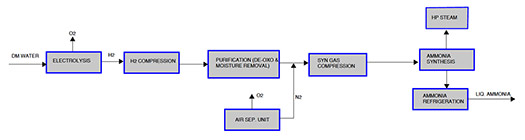
The front-end of the natural gas-based SMR process involves several catalytic steps and an elaborate CO2 removal unit, while the complexity level of the green NH3 front-end process is relatively low. The back-end process from synthesis gas compression to refrigeration is quite similar in both routes of NH3 manufacturing.
Process design considerations. The NH3 plant capacity will primarily determine power consumption requirements. This energy would be utilized from the green electric grid or captive energy farms. For continuous plant operation, sufficient battery banks must be available to supply electric power during the night when solar production dwindles, or another unconventional energy source must be available. The most important consideration for green NH3 projects is arranging green electric power.
The specific power consumption of a green NH3 plant can range from 9.2 MM Kcal/metric t–9.5 MM Kcal/metric t NH3 (ASU energy requirement included), out of which approximately 85% will be required for electrolysis and the rest for compression and pumping. Thus, a 1,000-metric tpd green NH3 plant will require approximately 450 MW of electric power. Contrastly, a natural gas SMR process can consume energy in the range of 6.5 MM Kcal/metric t–7.8 MM Kcal/metric t (mostly natural gas as feedstock and fuel), depending on the licensor processes and features. However, the green NH3 process is the winner regarding carbon footprint.
Electrolyzers. H2 is produced in electrolyzers operating at atmospheric pressure or under pressure with the help of demineralized water. The produced oxygen can be compressed, transported via pipeline, liquified and transported by tankers, or vented to the atmosphere.
There are two established electrolyzer technologies for NH3: alkaline and proton exchange membrane (PEM) electrolyzers. Both have pros and cons and some of the criteria that should be considered for selection are:
- Efficiency: KWhr of energy consumed per kg of H2 produced.
- Operating pressure: A pressurized electrolyzer will lead to less or no compression for H2. Ideally, the electrolyzer should be operating at the pressure required for gas to meet the synthetic gas (syngas) compressor suction pressure. Gas compression can be expensive and burden the electric load compared to high-pressure water pumping to the electrolyzer.
- Life of the cell/stack: An alkaline electrolyzer has more operating life than a PEM electrolyzer. The electrolyte [20%–30% potassium hydroxide (KOH) solution] required for an alkaline electrolyzer has 8 yr–10 yr of life and will require replacement.
- Size: The size of an electrolyzer skid in terms of kg/hr production capacity impacts its footprint. Parallel electrolyzer skids will lead to greater overall footprint requirements. The sizes of electrolyzers available in the market are evolving to make them more cost effective. A single electrolyzer cannot fulfill the requirement of H2 production required for manufacturing NH3.
- Capital expenditure (CAPEX): PEM electrolyzers are more expensive due to electrode metallurgy costs.
- Cooling water requirement: Cooling water is required for cooling H2 and water. Oxygen may also be cooled to knock off and recover water from the gas.
- Location: The choice to install an electrolyzer skid indoors or outdoors should be based on the supplier’s recommendation. Indoor installation can challenge the building design in the case of a pressurized electrolyzer.
Oxygen acts as a poison for NH3 synthesis catalysts; therefore, guaranteed H2 purity offered by the electrolyzer supplier will be very important. The purity should be a minimum of 99.5% H2.
The H2 production capacity of the electrolyzers is dependent on whether a portion of H2 will be stored in a pressurized tank (typical 240 barg) or underground salt cavern storage (if available). How fast the electrolyzer can ramp up or down in response to the plant load variation is another factor that should be addressed with the electrolyzer supplier.
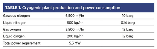
ASU. The high-purity nitrogen required for NH3 synthesis is produced from a cryogenic ASU, and its nitrogen production capacity will depend on the NH3 plant’s production rate. The ASU will produce gaseous and liquid oxygen, and its offtake to nearby industries should be explored.
Care should be taken while defining the contaminants in the atmospheric air near the project site. This is due to various incidents that have occurred inside the cryogenic cold box due to insufficient contaminant definitions in the air. One example was a forest fire polluting the atmospheric air and the design did not consider such contaminants. Typical cryogenic plant production and power consumption are given in TABLE 1 for 10 parts per million (ppm) of oxygen in nitrogen product purity level.
H2 produced from electrolyzers will contain residual oxygen and moisture. H2 may have to be compressed (depending on the electrolyzer operating pressure) to 15 barg–20 barg to remove some moisture in knock-out drums after cooling. Compressed H2 will be sent to a deoxo unit, which removes oxygen catalytically by reacting with H2 to form water and absorbing the water in a desiccant. The compressor discharge pressure should be determined based on the syngas compressor’s NH3 synthesis loop pressure and suction pressure.
H2 is compressed by the suction pressure of the syngas compressor that handles a mixture of H2 and nitrogen to raise the pressure further. The centrifugal compressor will be less efficient than the reciprocating type and will have difficulty compressing the low molecular weight of H2. Since lubricating oil can harm the NH3 synthesis catalyst life, oil-free reciprocating compressors should be considered.
Consideration should also be given to the turndown operation of electrolyzers with the H2 compressor and deoxo unit. One option could be the parallel configuration of multiple H2 compressors and deoxo units aligned with multiple electrolyzer stacks. Electrolyzers can operate at a turndown rate of 5%–15% depending on the type of electrolyzer. Removing each electrolyzer stack with one H2 compressor and deoxo unit can reduce the plant production rate depending on electric power availability. Alternatively, a large H2 compressor with capacity controls and a single deoxo unit can be used.
If a single deoxo unit is chosen, it can be configured at the syngas compressor interstage. At higher pressures, its size and footprint requirements can be reduced. However, coordination with the compressor vendor will be required to design the compressor system. Purified H2 and nitrogen storage may be required at high pressure due to the following:
- The front end can ramp up or down quickly, but NH3 synthesis cannot ramp up or down fast enough.
- For peak load shaving, the storage may help optimize back-end (NH3 synthesis) plant load operation, avoiding/reducing peak demand charges imposed by the electric power company.
- Any small duration outage in the front end of the process can facilitate continued NH3 production with at least 40% turndown to keep the NH3 synthesis reactor alive.
H2 and nitrogen gases must be compressed further to the storage pressure. Higher pressure will reduce the size of the storage tanks and more gas mass can be stored, but this requires more compression energy. While feeding H2 and nitrogen from the storage tank pressure levels to the syngas compressor suction, pressure letdowns will waste energy. The optimum storage capacity and pressure level should be determined based on the desired NH3 production rate. The possibility and economics of recovering energy by employing gas expanders (and consequent cold energy recovery) can be explored. Frequent pressurization and depressurization of the tank may require special design considerations, and the vessel engineer should be consulted.
If the storage pressure is considered higher than the NH3 synthesis loop pressure, the NH3 process licensor should be consulted for the viability of connecting the storage tanks to the synthesis loop as makeup. The H2 and nitrogen mixture is then fed in a stoichiometric ratio to the NH3 synthesis loop in a controlled manner.
The only source of high-pressure steam production is from the waste heat boiler in the NH3 synthesis loop downstream of the NH3 reactor. Based on the 450°C reactor outlet temperature, steam superheater, waste heat boiler and boiler feed water preheater at the reactor outlet, medium-pressure steam (40 barg–45 barg) can be produced. This steam cannot be used to run the compressor turbines as it would necessitate a package fuel-fired boiler to supply steam to the compressor turbine for startup purposes, which will not be a possibility in a green NH3 facility.
Dual drivers with a steam turbine for normal operation and an electric motor for startup connected with the compressor [multiple stages/casing(s)] could be possible. Another option to utilize produced steam would be to run a steam turbo generator to produce electric power, which can supplement the plant’s power requirement. Since superheated steam will be required to run the steam turbine, a superheater at the outlet of the NH3 reactor will be required.
Contrary to the SMR-based NH3 synthesis loop with approximately 1% inert gases (argon and methane) in make-up syngas, the green NH3 synthesis loop will have a very low inert gas (ppm level). The boiling point of argon is between oxygen and nitrogen; thus, a very small quantity of argon would slip along with nitrogen coming out of the ASU distillation column. This will significantly lower the synthesis loop pressure and help reduce compression energy. A lower inert level in the loop would also impact NH3 synthesis kinetics favorably in the NH3 reactor.
The need for continuous high-pressure purging and an additional H2 recovery unit from the purge gas will be negated to maintain the inert level in the NH3 synthesis loop, contrary to the conventional NH3 plant. The dissolved argon with liquid NH3 going from the synthesis loop into the refrigeration unit would be enough to prevent inert build-up in the loop.
NH3 loop start-up heater. In conventional NH3 plants, a gas-fired startup heater preheats the compressed syngas before sending it to the NH3 synthesis reactor. In green NH3 manufacturing, an electrical heater will be used. The heater handles up to 40%–50% of the design syngas flowrate during startup, and the size of the electrical heaters will depend on the NH3 plant design capacity. Electrical heaters of 5 MW–6 MW capacity are available. There must be a push in the heater business to make bigger units due to the growing need for larger-capacity green NH3 projects.
Peripherals. Demineralized (DM) water is required for water electrolysis. Typical water conductivity will be less than 1.0 microsiemens/cm. The condensing turbine of the turbogenerator will return the condensate to the deaerator. DM water will be made up in the deaerator to compensate for the DM water consumption and losses. The low-pressure steam required for the motive steam ejectors (for the condensing turbine) and deaerator will be supplied by extracting steam from the condensing turbine at a low-pressure steam level or via a medium-pressure steam let-down station.
Nitrogen purging equipment and piping requirements will be supplied from the ASU. The ASU’s air compressor will also meet plant air and instrument air requirements. These requirements should be considered in the air compressor capacity determination. Cooling water will be required to produce H2 (and oxygen, if required) in electrolysis, compression, NH3 synthesis loop and NH3 refrigeration.
Takeaway. The green NH3 production process utilizing electrolyzers—discarded in the last century due to high energy consumption—is now returning to the forefront, requiring new considerations for the front-end process design based on green electricity. However, the back end of the NH3 process will be quite similar, with nuanced design changes. The H2 production capacity of electrolyzers is constantly evolving to reduce the number of electrolyzers required for a given NH3 production plant, thus reducing their cost. The ultimate design approach for green NH3 projects should minimize the OPEX and CAPEX with a high onstream factor for the plant. From an operational perspective, the green NH3 plant will be less complex due to the much simpler steam system and fewer catalytic reactors. The viability of green NH3 projects will remain dependent on arranging green electric power, considering its high electric power requirement.H2T
LITERATURE CITED
1 Gonzalez, R., “Worldwide gas industry goes full throttle,” PTQ Gas, 2022, online: https://ptqmagazines.digitalrefining.com/view/919450973/8/
2 Sakthivel, S., “Stability and durability of water electrolysers,” Decarbonisation Technology, February 2023, online: https://decarbonisationtechnology.com/article/145/stability-and-durability-of-water-electrolysers
3 Harrison, S. B., “Feedstocks and utilities for green hydrogen and e-fuels,” Decarbonisation Technology, May 2023, online: https://decarbonisationtechnology.com/article/163/feedstocks-and-utilities-for-green-hydrogen-and-e-fuels
4 Schmidt, W., Air Products and Chemicals, “ASU reboiler/condenser safety,” February 2006, online: https://dokumen.tips/documents/asu-reboilercondenser-safety-air-products-reboilercondenser-safety-this.html?page=1
5 Tiras, C., “Electrical process heating and a call for standard specifications,” Decarbonisation Technology, August 2022, online: https://decarbonisationtechnology.com/article/98/electric-process-heating-and-a-call-for-standard-specifications
About the author

SANJIV GOYAL has several years of experience in ammonia, syngas, gas processing, LNG, refineries and upstream oil and gas. He has worked in several operating and engineering companies in various roles. Presently, Goyal is working at Black & Veatch as a process engineer.
Related Articles
Connect with H2Tech
