Articles
H2 production through gas pressure utilization at natural gas transmission network stations
Process/Project Optimization
G. VALLIOS, METRON SA Energy Applications, Athens Greece
Metering and pressure regulating stations are used in gas transmission pipeline networks to measure gas flow, analyze gas composition at custody transfer points and/or reduce and control the flow pressure into the connected downstream pipeline networks. The pressure let-down principle is followed since gas is a compressible fluid, enabling downsized equipment to be adopted to convey the same amount of energy at a higher pressure with obvious cost benefits.
Consequently, the transmission of gas is achieved through high-pressure transportation pipelines, but the gas pressure is reduced at certain points, facilitating the consumption at lower pressure settings.
The gas network backbone typically consists of high-pressure transmission sections (90 barg−80 barg), transferring the gas to the medium-pressure networks (50 barg−19 barg), enabling the connection of large industrial consumers (e.g., power plants) or entire cities, whereas cities are connected to low-pressure grids enabling the gas utilization from smaller energy consumers, such as smaller industries and/or domestic consumers.
This is achieved with the pressure regulating streams of the gas stations at the battery limits of different pressure networks. The regulating streams throttle the gas flow and reduce pressure by converting the dynamic pressure energy to the kinetic energy of the gas. During this irreversible process, most gases—including the natural gas among them—cool down and absorb heat through their environment (Joule-Thompson effect). As a rule of thumb, for a pressure reduction of Δp=1 barg, natural gas temperature decreases by ΔΤ=0.5°C
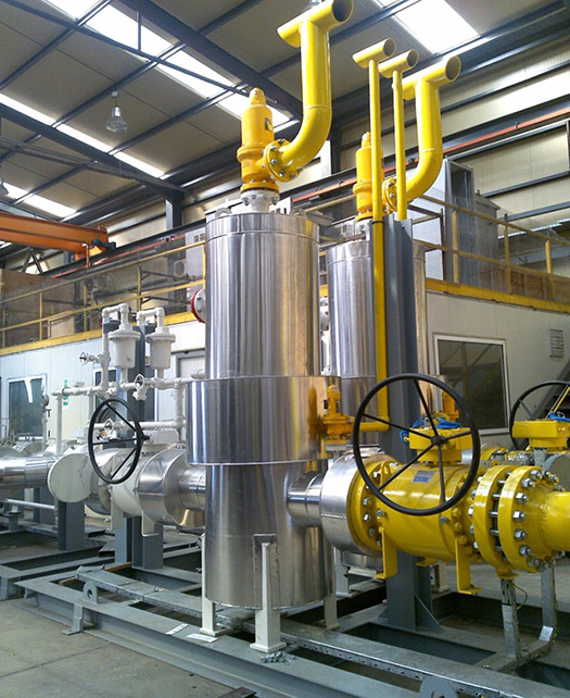
To compensate for the cooling effect, gas stations are equipped with gas heating systems (hot water shell and tube heat exchangers, water bath heaters, steam heaters, etc.), avoiding freezing conditions that can lead to condensation formation and equipment malfunction (FIG. 1).
Instead of wasting the dynamic energy, it can be utilized to produce electricity by engaging an expansion turbine driving electrical generator, which can replace the functioning of the pressure regulator (throttle valve). Assuming an isentropic expansion through the first thermodynamic law, the work which can be achieved is shown in Eq. 1:
W = ∫cp x dT (Eq. 1)
Cp is the specific gas heat at constant pressure, which depends on the gas composition, and dT is the gas temperature difference due to the gas expansion.1
Therefore, the in-line turboexpander can harness the energy waste, producing electricity, and the power generated can be utilized by an electrolyzer to produce hydrogen (H2), with the intent of blending it with natural gas at the gas station outlet.
Blending H2 and natural gas can significantly reduce greenhouse gas (GHG) emissions, since the combustion of the H2 does not produce any GHGs. This is under the assumption that the H2 is produced from low-carbon technologies such as renewable energy resources (e.g., wind, solar, biomass) or fossil resources with carbon capture and storage (CCS). The social and environmental benefits associated with blending H2 with natural gas are obvious. This will improve the environmental footprint by reducing carbon, sulfur and nitrogen oxides, and particulate matter emissions.
In the examined scenario, H2 is produced through harnessing the gas expansion waste energy in the regulating station, which can be considered resourceful production with environmental benefits. Additionally, such application can be economically subsidized by European Union (EU) programs for H2 production, enhancing the sustainability of natural gas supply systems, since natural gas can be utilized to produce green fuel.
Furthermore, a sustainable operation of conventional power plants can be achieved by fueling them with a mixture of blended gas and H2 instead of natural gas alone, reducing its atmospheric emissions and subsequently improving its environmental footprint.
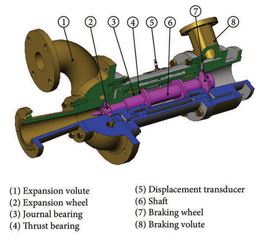
Technical features of the energy generation system. Pressure regulators can be bypassed by turboexpanders and utilize the difference in pressure to produce electricity through the rotation of the turbine shaft. High-pressure gas enters through the expander wheel, extracting the kinetic energy from the gas stream and triggering the wheel rotation, driving the electrical generator. The gas exits the expander section at a lower pressure and temperature. In this case, the temperature drop is much greater due to the gas expansion (FIG. 2).
This is proportional to the Joule-Thomson coefficient, where H is the gas enthalpy, 𝜕𝑇 the temperature drop and 𝜕𝑇 the pressure drop (Eq. 2):
𝜇𝐽 = (𝜕𝑇 / 𝜕𝑃)𝐻 = [(𝜕𝐻 / 𝜕𝑃)𝑇 ] / [(𝜕𝐻 / 𝜕𝑇/)𝑃 ] (Eq. 2)
The coefficient expresses the variation of temperature with pressure at constant enthalpy (adiabatic process) and is a negative figure for the gas as this is cooled during throttling operation. For infinitesimal fall of pressure coefficient becomes 𝜇𝐽 = 𝐶𝑝 𝜌, where ρ is gas density.
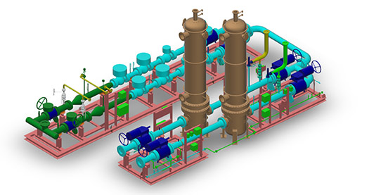
For this purpose, a system of heat exchangers with hot water as a heating medium is utilized, providing heat to the gas upstream of the turboexpander, balancing the cooling effect and ensuring that the gas temperature at the outlet will remain within the allowable limits—usually 25°C above the natural gas dew point (FIG. 3).
In the case of turboexpanders, the temperature drop due to the Joule-Thomson effect is much higher; therefore, the preheating temperature at the inlet is higher than the one in the case of the throttle valve. The electricity production can be calculated from the yearly consumption of the gas station by defining the average flowrates, inlet gas pressures and temperatures.
Other significant data for power production calculation is the inlet gas temperature (Tin gas), which is the isentropic efficiency of the turboexpander (ns=85%), whereas the overall efficiency—including the electrical conversion—is estimated ntot=70%, and the natural gas heating value is approximately ΔΗ=8,400kcal/Nm3.
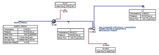
For example, a metering and pressure regulating station that delivers gas to a city is used. The station receives natural gas from a high-pressure gas network at a pressure of 70 barg and delivers the gas at the medium pressure gas network at a pressure of 20 barg. Therefore, the available Δp for the work generation by the turboexpander is Δp=50 barg.
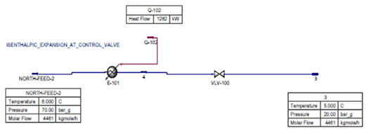
The average flowrate of the station is Q=100,000Nm3/hr. This regulating station—prior to the turboexpander utilization—consumes a heat of 1,300 kilowatt (kW) to compensate for the Joule-Thomson effect and produces null energy (FIG. 4).
However, after the turboexpander retrofit, the same station consumes a heat of 3,280 kW and produces 2,000 kW of electricity (FIG. 5).
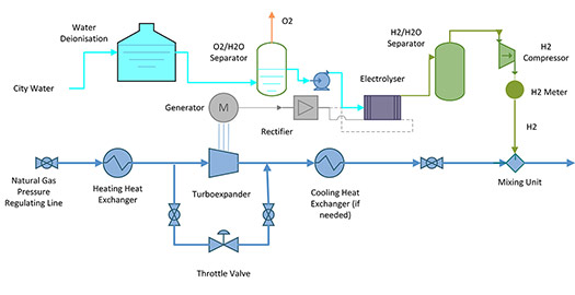
Technical features of the H2 production system. H2 generation can be obtained through a proton exchange membrane or alkaline electrolyzer, utilizing the electricity harnessed by the regulating station. In other cases of green H2 production, electricity produced from renewable energy systems (e.g., wind farm or photovoltaic parks), instead of transmitted through the grid, is consumed by the electrolyzer, inducing a disposal electricity cost as operational expenditure (OPEX).2
In this case, the electricity is produced from the wasted energy entailing a relatively much lower OPEX. The system consists of an electrolyzer, a rectifier (to convert the electrical current from alternative to constant, supplying the electrolysis cell), a water treatment system, oxygen and H2 separators, and a H2 compressor for the injection of the produced H2 inside the gas pipeline (FIG. 6).
The electrolyzer stack has the capability of 2-megawatt (MW) electrolysis power, exploiting the entire power generated by the turboexpander. The system will produce approximately 36 kg/hr (or 400 Nm3/hr) of H2.
In the electrolyzer, there are two separators connected to the cathode and anode. The cathode contains H2, and the anode contains oxygen, which is separated from the water used in electrolysis. The water comes from the potable water grid after a de-ionization process. The produced H2 is compressed in a gas compressor at a discharge pressure slightly higher than the pressure of the gas pipeline, enabling the mixing of the two streams.
The H2 is measured prior to the injection point inside the pipeline. Custody measuring incorporates a flow computer and gas chromatograph, which checks the H2 purity for the estimation of the H2 quantity for invoicing purposes.
H2 blending mixture properties. H2 has a high heating value of ΔΗΗ2=120,000 kilojoules (kJ)/kg and a low density of ρΗ2 = 0.089 kg/m3, compared to natural gas where indicative values are ΔΗNG = 48,000 kJ/kg and ρNG = 0.76 kg/m3 at ambient conditions.
The heating value of the mixture depends on the composition of the natural gas. H2 purity and H2 percentage in the mixture can be obtained by Eq. 3:
𝐻𝑚𝑖𝑥𝑡𝑢𝑟𝑒 = 𝛥𝛨𝑚𝑖𝑥 + ∑𝑥𝑖 x 𝐻𝑖 (Eq. 3)
Where:
Hmixture: Total enthalpy of the system after mixing
ΔHmix: Enthalpy of mixing
Xi: Mole fraction of component i in the system
Hi: Enthalpy of pure component i
Taking this into consideration, a 10% per mole fraction blending of H2 in a natural gas pipeline results in an increase of enthalpy of 2% for the gas mixture. Although the blending ratios are typically expressed in volumetric percentages, the H2 share to the increase of the gas mixture’s heating value and subsequently to the potential carbon dioxide (CO2) emissions savings is low due to the low volumetric energy density, which is roughly one-third of methane’s (CH4’s) energy density.
It is important to the energy offtakers that the combustion conditions and Wobbe index is ensured within the range of the end user’s operational conditions (e.g., gas turbine of a power plant). Since the mixture can be enriched to higher percentages of H2, it is possible to extract the H2 downstream of the gas pipeline section.
Economical features of the H2 production system. Regarding the economic analysis of the project, the following assumptions have been taken into consideration:
- The 2-MW electrolyzer’s CAPEX is estimated at €1,000/kW
- The turboexpander cost is estimated to be €500/kW
- The installation life expectancy is 20 yr
- No subsidies have been calculated, which can be granted and can significantly improve the investment’s viability
- The inflation rate is estimated 2%
- The replacement of the cell stack has been considered within the lifecycle
- The additional gas for heating required due to the Joule-Thompson effect is estimated to 67 Nm3/hr per 1 MWh of electricity produced. For a gas selling price of €40/MWh, the cost per produced H2 is €1.61/kg
- The electricity fee is considered €0/MWh as the complete power is conveyed to H2 and is not distributed to the grid
- The heating cost is calculated considering an average natural gas cost of €40/MWh
- Water cost is estimated to be €30/t
- When considering the CH4 substitution from H2 in the gas blending, CO2 emissions reduction is monetized. The monetizing cost of CO2 emissions is considered to be €9/t of CO2
- The CO2 emissions reduction as a social benefit is from the substitution of the kgs produced in the electrolyzer by CH4 fuel firing instead of pressure reduction utilization.
Based on these assumptions, the levelized cost of H2 (LCOH) is stipulated to the diagram (FIG. 7).
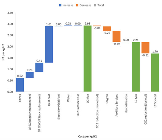
The maximum LCOH is estimated to be €2.93/kg. The generation cost of green H2 is in the range of €3.3/kg−€6.5/kg, and the cost of blue H2 averages €2.67/kg.3,4
Green H2 is produced by renewable power, mainly wind farms and photovoltaic plants. H2 production can be obtained from electrolyzers, which can run during periods of excess power production without introducing the power to the electricity grid. This elevates the technology as highly competitive when compared to other methods of production.
Capitalizing the externalities—like CO2 emissions reduction—can achieve a cost of €1.7/kg of H2, without inducing the investment subsidizing, which is expected to make the selection of such projects much more attractive.
The challenge is to utilize the technology, communicate with transmission system operators, set up the operational framework of gas networks and select gas stations with steady throughput during the year, ensuring continuous green H2 production which can be blended in the gas network, enabling the use of a much more environmentally friendly fuel.H2T
LITERATURE CITED
1 National Renewable Energy Laboratory, “Hydrogen blending into natural gas pipeline infrastructure: Review of the state of technology,” et.al, K. Topolski, E. P. Reznicek, B. C. Erdener, C. W. San-Marchi, J. A. Ronevich, L. Fring, K. Simmons, O. J. Guerra-Fernandez, B. Hodge and M. Chung, October 2022, online: https://www.nrel.gov/docs/fy23osti/81704.pdf
2 “Energy regenaration in natural gas pressure reduction station by use of gas turbo expander; Evaluation of available potential in Iran,” et.al, E. K. Ardali, E. Heybatian, October 2009, online: http://members.igu.org/html/wgc2009/papers/docs/wgcFinal00399.pdf
3 Hydrogen Europe, “Clean Hydrogen Monitor 2022,” October 2022, online: https://hydrogeneurope.eu/clean-hydrogen-monitor2022/
4 “The role of green and blue hydrogen in the energy transition–A technological and geopolitical perspective,” et.al, M. Noussan, P.P. Raimondi, R. Scita and M. Hafner, December 2020, online: https://doi.org/10.3390/su13010298
About the author
GIANNIS VALLIOS is a Board and Gas, Water and Energy Division member for METRON SA–Energy Applications. He is now involved with energy transition projects, including H2 utilization. Vallios has 30 yr of experience in natural gas, oil and energy design projects, detailed engineering and project management, integrating and delivering complete systems for fuel processing, and controlling and custody metering to the international market. Vallios earned an MS Diploma in mechanical engineering from the University of Patras in Greece, an MSc in energy and thermal power from Manchester University in the UK and an MSc in environmental engineering from the Hellenic Open University.
Related Articles
Connect with H2Tech
