Articles
The concern of CO emissions
Special Focus: Process/Project Optimization
D. CHAUDHURI, V. GUPTA and S. KUMAR, Fluor, Delhi, India
No refinery can operate without hydrogen (H2) because it is needed in all hydroprocessing technologies to remove sulfurous impurities and produce products at the correct specifications. With each passing day, the importance of H2 in refineries is increasing as crude oil gets heavier and more sour while product specifications are simultaneously getting tighter. Steam methane reforming (SMR) is still the most common method of H2 generation in a petroleum refinery. In SMR, a hydrocarbon feed reacts with steam to generate H2 via the following reactions (Eqs. 1, 2 and 3):
CnHm + nH2O ⇒ nCO + (n + m/2) + H2 – Heat (1)
CH4 + H2O ⇔ CO + 3H2 – Heat (2)
CO + H2O ⇔ CO2 + H2 + Heat (3)
The hydrocarbon feedstock can be natural gas, a liquid feed (e.g., naphtha) or a mixture of the two. FIG. 1 illustrates the overall H2 generation process by steam reforming.
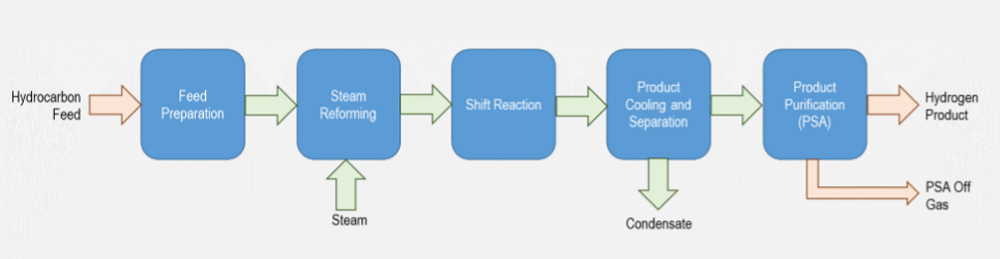
The feed purification section predominantly includes the hydrogenator reactor and the sulfur removal beds. The hydrogenator is used to remove any sulfurous components in the feedstock, while the sulfur removal beds are used to capture the H2 sulfides generated. This is an important section of the H2 plant, as the catalyst used for the main reforming reactions is extremely susceptible to sulfur poisoning.
In the next step, the actual conversion of the hydrocarbons to H2 takes place. If the units are processing a liquid or mixed feed, the first step of the reforming block involves the pre-reforming reactions, where the longer hydrocarbon chains are broken down into small hydrocarbon molecules, ideally methane (CH4). The hydrocarbon then reacts with the steam to produce H2 and carbon monoxide (CO) via Eqs. 1 and 2. The reactions are highly endothermic and require a reformer furnace to facilitate. The effluent from the reformer furnace is cooled down in a waste heat boiler to generate steam, while the flue gases from the furnace are utilized to generate steam or heat up process streams.
The cooled process gas is then passed through a shift reactor, producing more H2 using the water gas shift reactions as defined in Eq. 3. The reactor effluent is then further cooled, and condensed water (process condensate) is separated to generate a raw impure stream of H2. The H2 content of this stream would be in the range of 75 mol%, with appreciable mixed amounts of carbon dioxide (CO2), CO and unconverted CH4. This stream needs treatment to generate pure H2.
The product raw H2 stream is purified using pressure swing adsorption (PSA), which produces a pure H2 stream and a low-pressure purge stream called the PSA off-gas. PSA technology is based on physically binding gas molecules to the adsorbent material. The respective force acting between the gas molecules and the adsorbent material depends on the gas component, adsorbent material type, partial pressure of the gas component and operating temperature. A qualitative ranking of the adsorption forces is shown in FIG. 2.
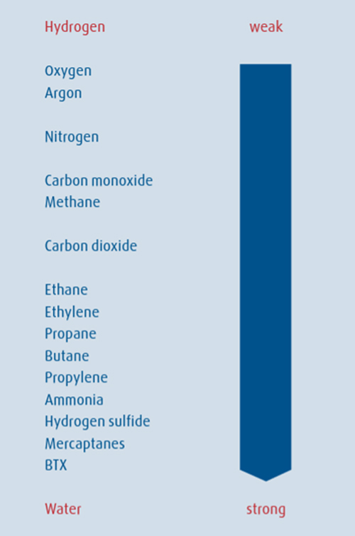
The separation effect is based on differences in binding forces to the adsorbent material. Highly volatile components with low polarities, such as H2, are practically non-adsorbable as opposed to molecules such as nitrogen (N2), CO, CO2, hydrocarbons and water vapor. Consequently, these impurities can be adsorbed from an H2-containing stream, and high-purity H2 is recovered. The PSA process works at a constant temperature and uses the effect of alternating pressure and partial pressure to perform adsorption and desorption. Since heating or cooling is not required, short cycles within the range of minutes are achieved.
A PSA plant consists of the adsorber vessels containing the adsorbent material, tail gas drum(s), valve skid(s) with interconnecting piping, control valves and instrumentation, and a control system for unit control. The PSA process comprises four steps: adsorption, depressurization, regeneration and repressurization.
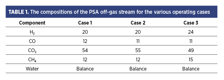
The PSA off-gas still contains appreciable amounts of H2 (~20%) even when the affinity of H2 towards the adsorbent material is minimal. Therefore, this gas still has the potential to be used as a fuel, although it is known to have a low heating index. The PSA off-gas is used internally in the H2 unit as the fuel for the reformer furnace. This off-gas also contains considerable amounts of CO, CH4 (~10%) and CO2 (50% or higher). The off-gas from the PSA is left at a very low pressure (typically 0.3 barg–0.4 barg) for the PSA unit to operate properly, limiting its usage elsewhere.
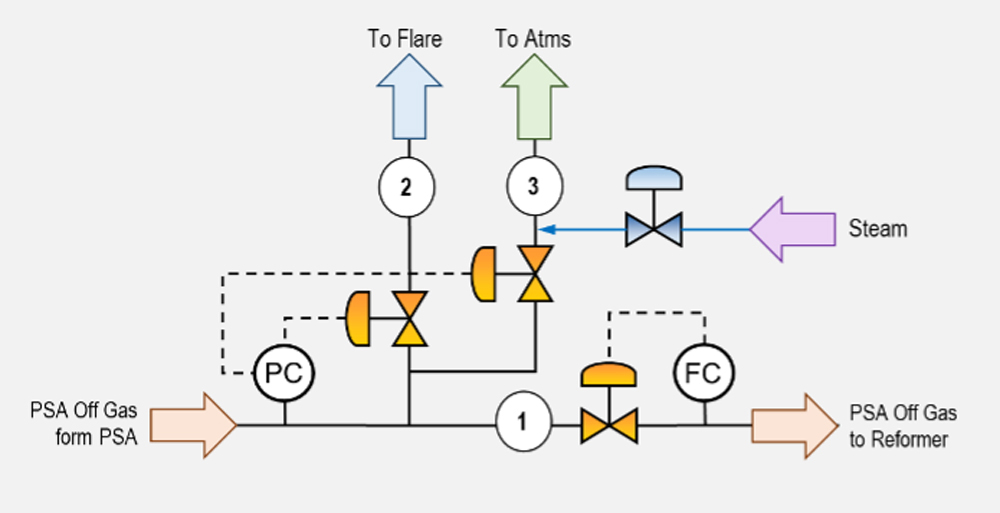
A typical design of the H2 generation unit includes a controlled flow of the PSA off-gas based on the downstream requirement. In a typical design of the H2 unit, all the PSA off-gas is consumed in the reformer furnace as the fuel, and only a “makeup” of an alternate fuel (natural gas, fuel gas) is consumed to maintain the required reaction temperature. The design of the PSA off-gas also includes a pressure control. If there is a disturbance in the downstream PSA off-gas user side, the off-gas is routed to the flare upon sensing a high backpressure in the PSA off-gas header. A venting system is also included in the design as a final layer of protection for the PSA beds against high back pressure (FIG. 3).
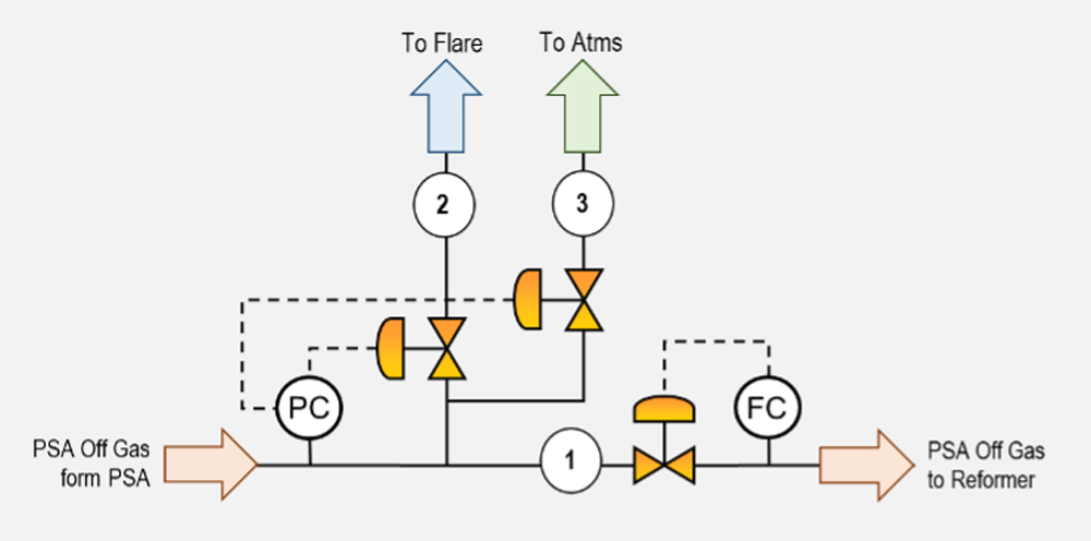
Under normal operating conditions, it is expected that all PSA off-gas is routed to the reformer furnace as the fuel; therefore, the normal route for the gas is through the line to the reformer (stream labeled 1 in FIG. 3). If there are downstream disturbances or the reformer is unable to consume all the PSA off-gas, the PSA will generate excess gas, which must be vented out. The options are to vent this gas through the flare header (stream labeled 2 in FIG. 3) or to the atmosphere via stream 3 in FIG. 3.
The venting operation happens automatically, based on the pressure on the system. When the pressure in the line increases, the pressure controller first opens the vent valve on the flare line. After fully opening the flare vent valve, the vent valve on the line to the atmosphere also opens in case the pressure continues to rise. This venting is also needed during the startup phase of the plant or unit when the PSA is gradually taken online, and the condition of the PSA off-gas is not stable. The alternative to allowing the gas to go to the atmosphere is typically included in the design since the normal operating pressure the venting requires to start is very low (in the range of 0.25 barg–0.3 barg), which may limit its venting capacity to the flare header.
CASE STUDY DATA
The case study reported in this article also involves a H2 plant with its PSA off-gas venting system and overpressure protection control, as shown in FIG. 3. TABLE 1 shows the composition of the PSA off-gas stream for the various operating cases for the H2 plant.
A unique condition for this case study is that the flare header pressure was on the high side, especially during the plant startup when multiple units were venting into the flare system. The flare header pressure was expected to be around 1 barg. Thus, during the startup phase of the H2 plant, the PSA off-gas was vented to the atmosphere for a prolonged timeframe.
Even when the PSA off-gas had a considerable amount of H2, the main concern was the off-gas releasing CO to the atmosphere (~10 vol%), impacting the toxicity exposure to the field personnel. The immediate danger to life and health (IDLH) of CO is considered as 1,200 parts per million (ppm), with a short-term exposure limit of 200 ppm [60-min emergency exposure guidance levels (EEGL)] and 50 ppm (24-hr EEGL).1
The presence of CO in the gas vented to the atmosphere raises safety concerns for personnel. Various dispersion modeling studies were performed with multiple options, and the results showed that even when the off-gas composition was high concerning the CO, the PSA off-gas vent outlets met acceptable project standard dispersion levels. The following section details the emissions studies undertaken in the project. Two venting scenarios were included in the study:
- During normal plant operation with a venting flowrate of 100,000 normal cubic meters per hour (Nm3/hr) for 5 min
- During startup operation with a venting flowrate of 50,000 Nm3/hr for 20 min.
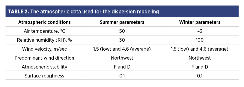
The CO concentration of 35 ppm (as per local emission guideline), 200 ppm [emergency response planning guidelines (ERPG)-1], 1,200 ppm (IDLH) were mapped in the dispersion modeling study, while TABLE 2 provides the atmospheric data used for the dispersion modeling.
The vent outlet in the plant is on top of the pipe rack 25.5 meters (m) above grade. The nearest operation/maintenance platform is 34 m above grade and 61 m from the vent outlet. The input data was fed into hazardous concentration modeling (HCM) and process hazard analysis software tool (PHAST) software.
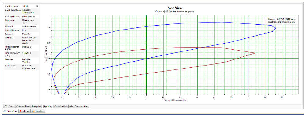
In FIG. 4, below the side view of the PSA off-gas stream, dispersion to the IDLH is shown for the Summer case (50ᵒC/30% RH) with the maximum relieving.
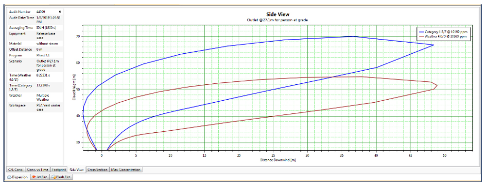
In FIG. 5, below the side view of the PSA off-gas stream, dispersion to the IDLH is shown for the Winter case (–3ᵒC/100% RH) with the maximum relieving.
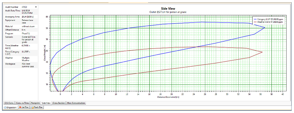
In FIG. 6, below the side view of the PSA off-gas stream, dispersion to the IDLH is shown for the Summer case (50ᵒC/30% RH) with the minimum relieving.
In FIG. 7, below the side view of the PSA off-gas stream, dispersion to the IDLH is shown for the Winter case (–3ᵒC/100% RH) with the minimum relieving.
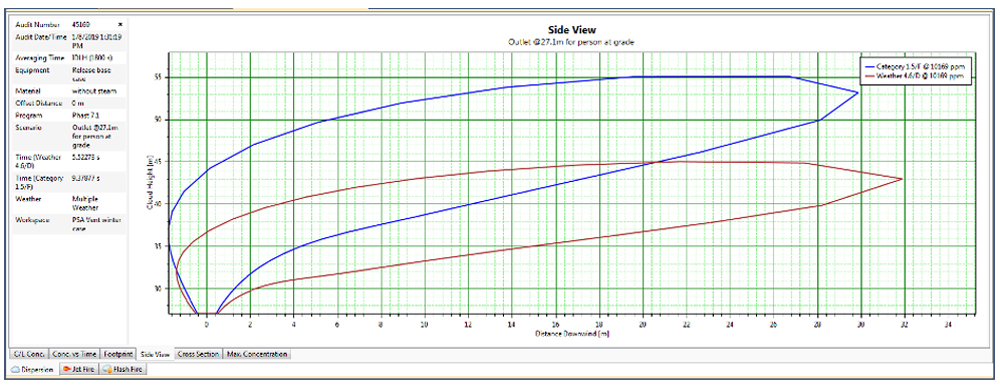
The following results have been established from FIGS. 4–7 (derived from PHAST software):
- During the 4.6/downwind (D)/Summer weather condition and maximum relieving (see red cloud), the centerline downwind distance is 1,200 ppm, the CO concentration maximum is 57 m in the horizontal direction and the (absolute) height is 53 m (27.1 m is the point of release).
- During the 1.5/F/Summer weather condition and maximum relieving (see blue cloud), the centerline downwind distance is1,200 ppm, the CO concentration maximum is 63 m in the horizontal direction and the (absolute) height is 69 m (27.1 m is the point of release).
- During the 4.6/D/Winter weather condition and maximum relieving (see red cloud), the centerline downwind distance is 1,200 ppm, the CO concentration maximum is 49 m in the horizontal direction and the (absolute) height is 51 m (27.1 m is the point of release).
- During the 1.5/F/Winter weather condition and maximum relieving (see blue cloud), the centerline downwind distance is 1,200 ppm, the CO concentration maximum is 48 m in the horizontal direction and 66 m the (absolute) height is 66 m (27.1 m is the point of release).
- During the 4.6/D/Summer weather condition and minimum relieving (see red cloud), the centerline downwind distance is 1,200 ppm, the CO concentration maximum is 36.5 m in the horizontal direction and the (absolute) height is 44 m (27.1 m is the point of release).
- During the 1.5/F/Summer weather condition and minimum relieving (see blue cloud), the centerline downwind distance is 1,200 ppm, the CO concentration maximum is 37 m in the horizontal direction and the (absolute) height is 55 m (27.1 m is the point of release).
- During the 4.6/D/Winter weather condition and minimum relieving (see red cloud), the centerline downwind distance is 1,200 ppm, the CO concentration maximum is 32 m in the horizontal direction and the (absolute) height is 43 m (27.1 m is the point of release).
- During the 1.5/F/Winter weather condition and minimum relieving (see blue cloud), the centerline downwind distance is 1,200 ppm, the CO concentration maximum is 30 m in the horizontal direction and the (absolute) height is 53 m (27.1 m is the point of release).
- The nearest operating platform from the point of release is 34 m in height and 61 m in horizontal distance. The height of the 1,200-ppm toxic clouds is significantly distant (> 15 m), and the IDLH cloud never reaches this distance.
- Another platform is on the reformer stack at 45 m in height and 104.5 m away from the point of release. The CO IDLH does not reach this platform.
Therefore, plant personnel are not exposed to unacceptable (1,200 ppm) IDLH toxic levels in areas where they may be present (ground levels and platforms) in case PSA off-gas is released into the atmosphere. However, it is well understood that dispersion modeling makes assumptions to build a scenario that could be different in real plant operations. This study is limited to a few scenarios of meteorological conditions, composition and release conditions, and the anticipated presence of personnel at the plant controls and in the field with the ability to make accurate decisions.
The study aimed to aid plant operations in making necessary plant operations and emergency response guidelines if a release occurs. The mitigation measures include:
- Providing personal protective equipment, including portable CO detectors
- Having alarms and announcement provisions in the plant to alert personnel to move away from the area where venting has begun and dispersed gas in appreciable concentrations could collect
- Starting a steam ring as soon as possible.
Additional design modifications were proposed to include an automatic steam injection into the vent stream to further dilute the toxic gases (FIG. 8). The steam purge would open automatically when the atmospheric vent valve opened. Steam would further act as the diluting agent and would have the potential to decrease the concentrations of CO once it starts to vent to the atmosphere.
Another small modification was proposed on the overall hydrocarbon flare system, where the flare was also designed with a “staging” concept to have lower pressures in the flare header when there is no major relief in the refinery.
Takeaway. Atmospheric emissions from process streams under abnormal or rare scenarios always require careful verification. Even small quantities of hazardous components in the process stream, when vented to the atmosphere, may prove potent and have the potential to cause significant consequences. Detailed analyses and studies of all such vent streams must be conducted to assess the extent of emissions and the level of toxicity. The studies must undertake practical operating and upset conditions, and must not be too conservative. Based on the results of such studies, adequate actions and design modifications must be made to provide a safe and operable design.H2T
About the authors

DEBOPAM CHAUDHURI is a process engineer for Fluor New Delhi with more than 21 yr of experience in petroleum refining, petrochemicals and upstream projects. He earned a BS degree in chemistry and chemical engineering from the University of Calcutta.

VIVEK GUPTA has more than 30 yr of rich experience in design safety and fire protection engineering for project execution globally, serving clients ranging from oil and gas, chemicals, mining and metals and power sectors in government and private setups. He has been with Fluor New Delhi for more than 15 yr, providing safety and fire protection design services to projects and leading in developing the HSE engineering discipline as an organization goal.

VENKATA SRAVAN KUMAR is a process engineer for Fluor New Delhi with more than 15 yr of experience in petroleum refining, petrochemicals and fertilizer projects. He earned a BS degree in chemical engineering from Jawaharlal Nehru Technological University.
LITERATURE CITED
1 Centers for Disease Control and Prevention, “Carbon monoxide,” online: https://www.cdc.gov/niosh/idlh/630080.html
Related Articles
Connect with H2Tech
