Articles
Five essential tips for building efficient H2 fluid systems
Special Focus: H2 Equipment and Services
A. DOMÍNGUEZ, Swagelok Company, Zurich, Switzerland
The search for viable alternatives to fossil fuel energy sources is accelerating with each passing year. As governments strive to reduce greenhouse gas (GHG) emissions in transportation, industry and other segments of the economy, hydrogen (H2) is increasingly gaining support as one promising alternative that could drive an energy and power revolution. From transportation and material handling to stationary, portable and emergency backup power, H2 is proving useful in various applications, and industries everywhere are taking notice.
However, much of the knowledge about how to build an efficient energy system comes from the traditional oil and gas industries and is incompatible with the design of a H2 energy system. The shift to H2 requires a complete reimagining of how to design and incorporate critical features in the fluid systems that handle, transport, store and dispense the gas to ensure continued safety and reliability. This article highlights five considerations for engineers charged with building an effective, efficient H2 system.
#1: Consider the end user. H2 energy systems differ significantly from their fossil fuel counterparts [e.g., gasoline, compressed natural gas (CNG)] because the fuel is much closer to the end user. For most other fossil fuel delivery pipelines, the fuel remains out of sight for consumers. Processing and transportation are handled by professionals who understand the risks.
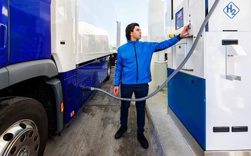
In contrast, H2 fuel systems put the consumer front and center. The vehicle they are driving contains a H2 fuel cell, requiring them to transmit high-pressure gas into their vehicle through a convenient dispenser (FIG. 1). Although H2 poses little risk to the environment because of its non-toxic properties and low volatility, it is combustible and could explode if the fuel transmission system is not designed properly.
However, one advantage H2 offers over its fossil fuel counterparts is that it will not explode unless oxygen concentrations in the air range between 4% and 75%. In contrast, gasoline can explode with oxygen concentrations in the air between 1.4% and 7.6%, making it significantly more volatile. In addition, H2 requires higher temperatures than gasoline to ignite. Once that ignition occurs, a H2 fire is less likely to spread because the surrounding air is cooler.
Concerns about how H2 is transported—under significant pressures—are often the result of misunderstanding the H2 tank’s construction and its surrounding transportation systems. Pressurized gas tanks have been in use for decades, as they are the preferred method to transport H2 for use in industry. Monitoring devices analyze systems within H2 dispensers—from hoses and valves to the storage tank itself—both while in standby and dispensing to immediately detect any possible H2 leakage.
The quick detection and remediation of possible leaks make H2 dispensing much safer than traditional fossil fuel dispensing. In the unlikely event that an unabated leak does occur, H2 is 14 times lighter than air and will quickly disperse into the atmosphere, reducing the chances of it igniting at ground level. This means consumers are generally safer around H2 than they are around more traditional gasoline or CNG dispensers.
#2: Minimize potential leak points. Leaks can be costly in any industrial fluid system, but nowhere is that more apparent than in H2 delivery systems. H2 presents an unusual challenge because of the size of its molecules, which are extraordinarily small and can escape through the tiniest of crevices. Since most fuel delivery systems in existence mirror gasoline or CNG dispensing systems, the components are not necessarily designed to handle a gas like H2.
H2 delivery systems require smarter designs to minimize leak points. These designs should reduce the overall number of individual connections and promote tube bends instead of adding more connections (FIG. 2). Working with an experienced partner when designing H2 systems provides valuable insight and training for engineers to optimize leak tightness.

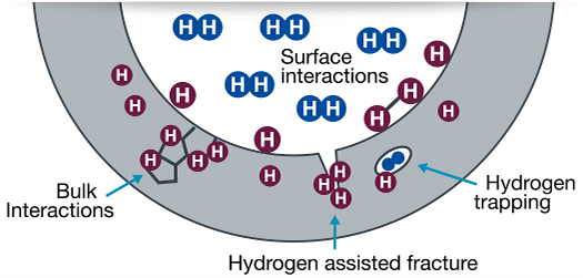
#3: Use high-quality stainless steel. In addition to leaks, small H2 molecules can cause a condition known as H2 embrittlement, which reduces a metal’s ductility and resistance to fracture and fatigue. Left unchecked, H2 embrittlement can cause widespread system failures that ultimately pose real-world safety, operational and financial risks.
H2 embrittlement is caused when H2 molecules diffuse into the surrounding metal. The higher the strength of the materials used in the system, the more severe the H2 embrittlement can become. Austenitic stainless steels are characterized by their face center cubic (FCC) crystal structure, moderate strength and naturally high ductility. While stainless steels are generally more compatible with H2 than many other metals, not all resist H2 embrittlement equally. Selecting the right material can prevent H2 embrittlement (FIG. 3).
In most cases, H2 systems should be designed using high-quality 316 stainless-steel tubing materials, which traditionally operate very well at containing H2 molecules and offer good performance over the system’s lengthy service life. More specifically, stainless steel used in H2 systems should have a higher nickel content.
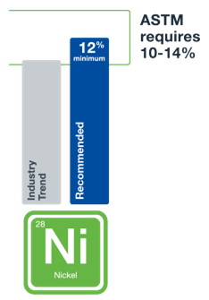
Stainless steels containing elevated levels of nickel can deliver optimal performance in H2 systems. The American Society for Testing and Materials (ASTM) requires a minimum of 10% nickel in 316 stainless-steel formulations, but 316 stainless steels with a minimum of 12% nickel is better for the unique challenges posed by H2 (FIG. 4). Nickel content helps stabilize the microstructure of stainless steel, enabling it to be more resistant to H2 embrittlement.
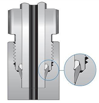
#4: Optimize your tube fittings. Because of their experience with oil and gas systems, industry engineers often specify traditional cone and thread fittings in H2 systems. However, this standard approach can pose potential problems due to H2’s demands. As discussed, H2 molecules differ from gasoline or natural gas molecules. Because H2 molecules are so small, they require tube fittings that are specifically tailored to handle their structure. This reemphasizes the need for engineers to take a completely fresh approach to design if they expect H2 systems to remain leak-tight and safe (VID. 1).
As an alternative to cone and thread fittings, compression fittings are engineered specifically for use in H2 applications and maintain ideal pressure ratings of up to 1,050 bar (FIG. 5). Since their introduction, compression fittings have been used by designers in a myriad of industries and applications. Often available in high-quality, stainless-steel options, their versatility and H2-specific design make them the optimal choice for H2 systems.
Additionally, compression fittings can save on labor costs because they are easier and quicker to install than traditional cone and thread fittings, primarily because they require fewer tools.
While technicians must still deburr and square-cut tubing to work with compression fittings, the fittings feature preassembled cartridges that make inserting the tubing much easier. Technicians can feed the tubing into the compression fittings—consisting of a nut, two ferrules and a plastic arbor—and turn it to complete the connection in seconds. Once checked with a gap inspection gauge to ensure a tight fit, the assembly is complete and ready for immediate use with pressurized H2.
#5: Consult with experts. As revolutionary as H2 is as a clean energy source, building the necessary infrastructure can seem overwhelming at first. Infrastructure developers, vehicle original equipment manufacturers (OEMs) and other parties are working overtime to deliver reliable solutions that will propel the industry forward, but solutions already exist today.
Operating in the rapidly expanding clean energy space and developing systems to handle H2 gas does not have to be difficult to understand with the right collaborator. It is recommended to work with a partner with specific H2 knowledge to offer advice on the most effective and efficient methods to make systems as flawless as possible. Your partner should be able to make product recommendations based on specific needs (FIG. 6), as well as offer materials science expertise and expert engineering assistance. By taking advantage of this industry expertise, engineers entering the world of H2 system design can ensure their systems are well-suited to handle and deliver H2 now and in the future. H2T
About the author

ANA DOMÍNGUEZ is the Engineering Services Supervisor - Clean Energy for Swagelok. She has worked for Swagelok for 11 yr and previously held roles as an application and field engineer. Domínguez has been in the clean energy engineering business for more than 15 yr and is familiar with identifying clean energy applications and services, troubleshooting, designing for optimized systems and innovative solutions. She is based in Zurich, Switzerland and earned an MS degree in chemical engineering and energy management and technology.
Related Articles
Connect with H2Tech
