Articles
The path to integrity readiness and the role of ILI inspections—Part 2
Inspection, Maintenance, Reliability and Safety
J. SUTHERLAND, Baker Hughes, Calgary, Alberta, Canada
As global industry targets carbon emissions reductions, the envisaged use of hydrogen (H2) as a primary energy medium is underway. Like other energy sources, H2 must be generated, stored, transported and finally consumed.
Pipelines are a highly cost-effective method of transportation, and existing pipeline infrastructures are being assessed for their suitability to transport H2 around the globe, blended within natural gas transport or as pure H2.
The nature of natural H2 itself as an energy medium brings new considerations in its handling throughout its lifecycle. Using pipelines as a primary means to transport H2 directly infers alternative and additional requirements for public safety and pipeline integrity beyond the natural gas hydrocarbon infrastructures of the last 80 yr.
There is anticipation that governmental and industry groups will convert and utilize substantial portions of the existing hydrocarbon infrastructure for H2.
Pipeline integrity principles and knowledge in the conversion of service and ongoing maintenance may be directly applied in many cases, while others may be adopted with some specific validation. These principles include threat management practices and known techniques for detection, mitigation and prioritization, leading to the mitigation (or removal) of a threat.
Such practices also include forecasting of pipeline integrity in the future, namely through methods for time-dependent flaw growth and remaining life predictions. A primary method in quantitatively assessing current and forecasting future pipeline integrity states is inline inspection (ILI).
Part 1 of this article, which appeared in the November/December 2024 issue, discussed pipeline integrity, threat management practices and the use of ILI within some stated presumptions for the mass-transport of H2 in pipelines.
As cracking threats gained prominence in integrity planning, ILI and assessment methods were initiated and evolved. Attempts to apply non-destructive techniques began in the 1970s, with commercial systems pioneered and introduced by the author’s company for ultrasonic crack detection (USCD) for liquid pipelines in the 1990s and electromagnetic acoustic transduction (EMAT) for gas pipelines in the 2000s. Integrity programs since then have evolved to reliably use high-performance crack ILI systems.14,18,19,20
Reported features from ILI related to cracking include “crack-like,” “crack field” and “weld anomalies” as the primary feature types of interest as axially oriented features (where a rupture threat from hoop stress is the expected failure mode). EMAT may also include indicators of localized coating damage.
EMAT ILI systems for crack detection and characterization are available today across most diameters of long-distance pipelines (8 in.–42 in.) (FIG. 5).
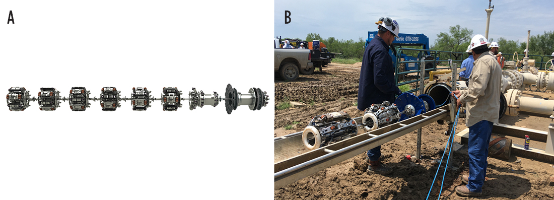
An ironic factor of early EMAT systems was their inability to discriminate material flaws and discontinuities from cracking.20,21 Today’s EMAT systems address and report discriminated features distinctly. For the early detection of stress concentrators—as preferred in the blended H2 scenario—the identification of inclusions, laminations and manufacturing flaws becomes preferential in collected data. This ability is an example of the potential evolution of capabilities.
It is envisaged that crack ILI will continue to evolve with H2 pipelines as well as form part of a robust integrity management program.
A core principle of an engineering critical assessment (ECA) of cracks [including stress corrosion cracking (SCC), seam weld cracks, girth weld cracking, laminations and weld anomalies] is based in fracture mechanics and fatigue crack growth methodologies,10 as well as an understanding of reported ILI features and interpretations such as crack profiling and crack field statistics.14
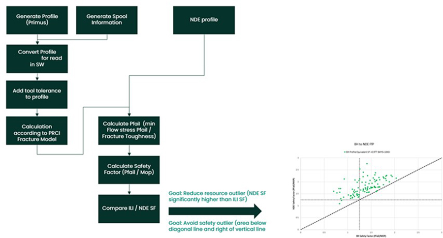
Updates to ILI crack profiling were recently evaluated and validated for achieving reduced conservatism in fitness-for-service assessments (FIG. 6).18 Such approaches would apply to the validation of a cracking assessment in H2 pipelines.
Hard spots. Hard spots are localized areas of material in pipes that are typically of a higher “hardness” than the line pipe specification. As material hardness is identified as a potential threat susceptibility condition for blended H2 operations, the identification of hard spot areas must include the higher risks of failure from defects due to a localized reduction in material fracture toughness.
ILI technologies designed specifically for localized material difference detection have existed since the1990s—early ILI technologies that were sensitive to localized material differences have been in use since the 1970s. The most common measurement approach is from remnant magnetic field detection and interpretation.
An example of an ILI signal response for a confirmed hard spot area is shown in FIG. 7. Note that signals are distinctive and repeatable. In some cases, other material impurities may also be detectable.
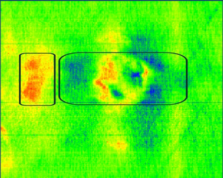
Detected and reported areas of interest may also then be aligned with ILI crack, corrosion, deformation and strain data for a more comprehensive evaluation and assessment.
Corrosion and gouging. Monitoring for corrosion and external damage (mechanical damage) remains a prominent activity for pipeline integrity as it predicates early detection of conditions—primarily as corrosion and volumetric wall anomaly characterization, but also for external cracking (SCC) susceptibility.
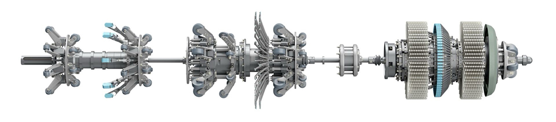
As with cracking threats, the threat of corrosion or gouging can be an indicator of cracking initiation and accelerated embrittlement crack failure, even from internally permeated H2. For gas pipelines, high-performance magnetic flux leakage (MFL) is recognized as the most reliable means of ILI inspection for corrosion and gouging/damage threats (FIG. 8).
With the presumed, more conservative acceptability criteria for the case of any flaws in H2 pipelines, the presence of any such flaws through the detection by ILI is presumed to trigger response and remediation activities. Defect specific sizing tolerances per reported defect have been recently introduced.
Defect tolerances provide a better understanding of risk and how certain defects can jeopardize pipeline safety and economic viability. Such methods will certainly be advantageous to the critical assessment of metal loss features in the presence of H2.
Advanced MFL systems have the capability for girth weld anomaly assessment, where circumferential crack-like features may be detected and reported.
Pipeline strain. Pipeline force cycling may not be caused solely by pressure: external forces/geotechnical forces may also cause pipeline damage, even with low cycling frequencies.
Today’s MFL ILI platforms are typically run with associated high-performance inertial measurement units (IMUs) to collect motion measurements in the pipeline—this technology was pioneered in the late 1980s.22 This inertial measurement data can be processed to provide continuous GPS location data of the center line of the pipeline and independent insight to characterize dents and other deformation features that may be present and interpret representative bending strain (curvature) of the pipeline at all points.23
Abnormal or unexpected levels of bending strain are indicators of external force/geotechnical force on the pipeline that may pose an imminent threat.
Primary uses for this method include geotechnically active areas (prone to landslides), areas near active geological faults or areas prone to large pipeline movements due to seasonal changes (e.g., muskeg/swamp conditions), offshore oceanic forces or ground frost-heave (e.g., in northern Canada and Alaska).24
When strain events coincide with time-dependent flaws (i.e., cracking, corrosion) such as those reported by MFL or EMAT systems, a more detailed engineering assessment must be considered, as assessments of time-dependent flaws in isolation are not applicable.25
Longitudinal strain. New ILI technology provides independent reporting of longitudinal strain that differs from conventional ILI IMU methods.26 The technology grew from a need to monitor for geohazard conditions beyond bending strain itself, such as potential buckling and wrinkling due to compressive forces.
After H2 introduction, the strain capacity of both base material and girth welds may be affected by H2 embrittlement, further increasing the risk of failure.
Girth weld assessment. Girth weld anomaly analysis involves MFL, IMU and strain measurement data to provide prioritized assessment for potential girth weld cracking. The identification of girth weld and spiral weld cracking based on advanced MFL ILI technologies was previously presented in literature.27
The adoption of these methods has grown recently in North America due to concerns of weld undermatching, where a high rate of girth weld failures has occurred since 2019 in the U.S. in both active and newly constructed pipelines.
Weld undermatching refers to the use of higher strength pipe than the stated specified minimum yield strength (SMYS), and inconsistent infield welding procedures leading to H2-induced cracking (HIC) and heat-affected zone (HAZ) softening, which significantly lowered the strain capacity for external forces and pipeline movement.28 As a H2-enabled issue, this should take more precedence for the integrity of H2-blended pipelines.
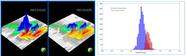
Predictive methods. All ILI data-based integrity assessment methods have practices for monitoring, growth prediction and remaining life estimation. Criteria for feature response and action to any identified change (growth) are based on operator and industry practices.
Such methods are necessary and should be adoptable for blended H2 pipeline scenarios. Fundamentally for ILI-based integrity programs, change detection is the basis for growth rate estimation (FIG. 9).
Within the evolution of pipeline integrity practices, flaw growth methodologies begin with corrosion. The author’s company was one of the principal authors of the primary industry guidelines for corrosion growth, including for deterministic and probabilistic treatments.29
The key goals of this methodology were to provide practical, consistent and systematic means to establish rates of growth. The methodology also identified opportunities to manage localized and varied growth rates within a defect population, the direct use of ILI-based signal change detection for more accurate growth rate estimation over ILI reported box methods, and guidance to address and validate “very high” or “improbable” rates of predicted growth in practical terms.30
The concepts and methods used to combat corrosion have since been adapted and applied for other threat types.
More organizations are implementing a more holistic assessment, where seemingly coincidental features and conditions to overall threats become clear in integrity programs that address a high volume and variety of scenarios for potential loss of containment through multiple means (FIG. 10).25,30
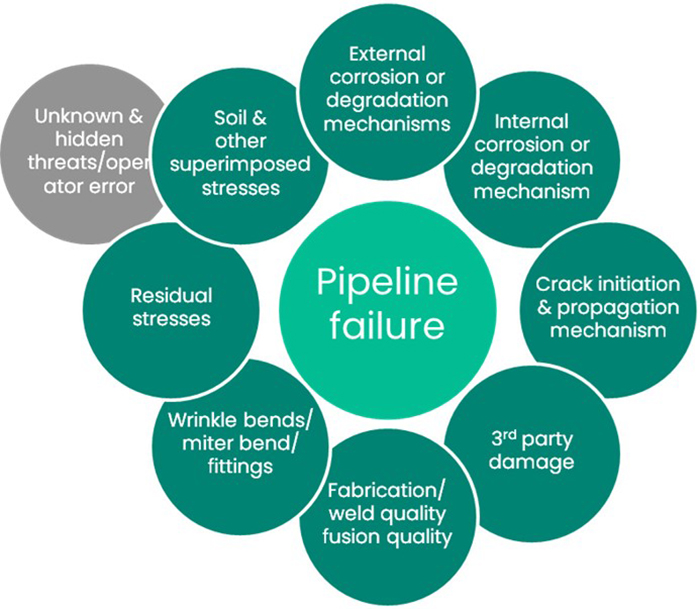
For H2 pipeline integrity, such an approach may be necessary over conventional natural gas methods, as the sensitivities of threats present different interactions and outcomes than hydrocarbon scenarios.
The use and application of machine-learning (ML) to both ILI signal interpretation and predictive analytics are significant to determine the reported features of any remaining defect populations. The availability of a variety of field validated samples leads to “big data” ML approaches.31,32,33
Such techniques and methods are naturally structured to manage large volumes of disparate data. They may also involve engineering calculations, practices and techniques as guiding principles, as well as independent explicit checks as boundary conditions of both historic and predicted results.
Tool readiness. In the context of ILI systems history, the readiness of ILI for blended or pure H2 pipelines originates in its readiness for other pipeline products. Over time, this has come to include methane gases, including hydrogen sulfide (H2S), refined liquid products, CO2 and nonhydrocarbon gases, aromatics (ethylenes), ammonia, etc.34
For the blended H2 case, the first consideration is safety. As with hydrocarbon pipelines, the areas of highest risk are typically the ILI/pigging launch and receiving systems of pipelines, where conditions of explosive gas, air and fuel are present.
The application of explosive atmospheres (ATEX) practices for pipeline ILI/pigging activities has been used for several decades—typically, the risk of a potentially explosive environment is mitigated (removed) by purging the facilities and access points of the explosive gas by using a non-flammable gas. Note: The decompression behaviors of H2 depend on its pressure and state, as would be found in ILI/pigging receiving traps.
In more extreme cases, there are similar and parallel procedures for ILI/pigging in sour-service (e.g., H2S) and hazardous product lines that have also been used for several decades.
For ILI tool system compatibility and run endurance within a blended H2 environment, the assessment is like elements of the pipeline itself with initial assessments dating back to the EU NaturalHy project of 2006–2009.3,34 A compatibility assessment includes the expected forms of H2 as gaseous, aqueous/ionic and scenarios of the presence of water, etc. It reviews the effects on materials [e.g., metallics, elastomers (seals)] and notably mimics topics noted in the conversion of service of a pipeline.
The monitoring of ILI vehicles and components for damage is already built into active maintenance practices. Materials and technologies for sealing (e.g., valves and compression equipment) are a source that ILI can also draw from, as such sealing materials become qualified for H2 service. Compatibilities can be addressed in ILI operations in H2 lines scaled to match hydrocarbon and/or other hazardous product pipelines.35–38
Operationally, there is a significant change in ILI tool flow dynamics depending on the percent of H2 in the product mix, particularly as it will affect gas compressibility, drag and bypass. For those ILI systems equipped with active variable bypass “speed control” systems, operations at high flowrates must be investigated and validated.
However, at one time, that was also an unknown concern of active ILI speed control systems for hydrocarbon gas pipelines. Today, such systems are used every day in pipelines around the world.
Takeaways. The progression of current hydrocarbon integrity and inspection practices has occurred for > 50 yr. From that experience, their applicability to blended H2 pipelines will also evolve to address the need of future energy transition pipelines.
Further stringent criteria and methodologies are envisaged for H2 pipeline integrity as H2 pipeline operations become more prevalent and common as core energy infrastructures.
Technologies developed and advanced for the monitoring of conventional pipelines form the basis for pipelines of the future energy transition. Current crack ILI inspection technologies are mature and will have carryover applications for H2 pipelines.
It is anticipated that the numerous technologies needed to manage the threats will provide a better understanding of critical flaw sizes and specific threats and will evolve to meet these potentially higher expectations. H2T
Editor’s note: This article was first published at the 36th Pipeline Pigging and Integrity Management Conference, February 2024. Organized by Clarion Technical Conferences. Used with permission. Part 1 of this article was also published in the June 2024 issue of our sister publication, Pipeline & Gas Journal.
LITERATURE CITED
1 European Union, “The European Hydrogen Backbone (EHB) initiative,” online: https://ehb.eu/
2 UK Government, “The ten point plan for a green industrial revolution,” November 2020, online: https://www.gov.uk/government/publications/the-ten-point-plan-for-a-green-industrial-revolution
3 NaturalHy consortium, “Preparing for the hydrogen economy by using the existing natural gas system as a catalyst,” 2009.
4 EU Hydrogen Alliance, “Hydrogen,” online: https://energy.ec.europa.eu/topics/energy-systems-integration/hydrogen_en
5 EU Commission, “A hydrogen strategy for a climate-neutral Europe,” August 2020.
6 Huising, O. J. C. and A. H. M. Krom, “H2 in an existing natural gas pipeline,” 2020.
7 ASME, “Hydrogen piping and pipelines,” online: https://www.asme.org/codes-standards/find-codes-standards/b31-12-hydrogen-piping-pipelines
8 European Industrial Gases Association, “Hydrogen pipeline systems,” 2014.
9 ASME, “Managing system integrity of gas pipelines,” 2020.
10 API, “Fitness for service,” 2021.
11 API, “Recommended practice for assessment and management of cracking in pipelines, 2021.
12 Ramboll, G. A., “Hydrogen as energy carrier—Comparison with gas and electricity,” 2021.
13 Adianto, R., J. Skow and J. Sutherland, “The benefits of accurate ILI performance on pipeline integrity programs for axial crack and metal loss corrosion threats,” 2016.
14 Slaughter, M., K. Spencer, S. J. Dawson and P. Senf, “Comparison of multiple crack detection in-line inspection data to assess crack growth,” 2011.
15 Canadian Energy Pipeline Association, “Stress corrosion cracking recommended practices,” 2015.
16 Pluvinage, G., “Mechanical properties of a wide range of pipe steels under influence of pure hydrogen or hydrogen blended with natural gas,” 2021.
17 Ronevich, J., C. S. Marchi, et al., “Hydrogen blending into natural gas,” Sandia National Laboratories, 2019.
18 Tappert, S. and L. Lamborn, “Leveraging ILI crack profiles,” 2023.
19 Bott, S., G. Foreman, Y. Hubert, P. Senf and J. Sutherland, “A study of crack detection ultrasonic calls relating to the different types of cracking discovered in pipelines when using crack detection ILI,” Pipeline Pigging and Integrity Management Conference, 2016.
20 Sutherland, J., S. Tappert, R. Kania, K. Kashammer, J. Marr, A. Mann, G. Rosca and C. Garth, “The role of effective collaboration in the advancement of EMAT inline inspection technology for pipeline integrity management: A case study,” International Pipeline Conference, Paper No. 2012-90021, 2012.
21 Tappert, S., D. Allen, A. Mann, M. Balzer and G. Van Boven, “Inline Inspection for crack in gas pipelines—Enhancements derived from 5 years of operational experience,” International Pipeline Conference, Paper No. 2008-64087, 2008.
22 U.S. Patent 4945775, “Interial based pipeline monitoring system,” 1990.
23 Czyz, J. and S. Wainselboin, “Monitoring pipeline movement and its effect on pipe integrity using initial/caliper inline inspection,” IBP575_03, Rio Pipeline Conference, 2003.
24 Czyz J. A., C. Fraccaroli and A. P. Sergeant, “Measuring pipeline movement in Geotechnically Unstable Areas Using an Inertial Geometry Pipeline Inspection Pig,” ASME 1st International Pipeline Conference, 1996.
25 Yablonskikh, Y., M. ElSeify and J. Dawson, “Strain demand and capacity assessment based on in line inspection of axial and bending strains,” Pipeline Pigging and Integrity Management Conference, 2021.
26 Dewar, D. and M. Elseify, “ILI of axial strain, technique, case studies and best practices,” Pipeline Technology Conference, 2017.
27 Feng, Q., B. Gu, J. Sutherland, C. Tao and Y. Wei, “Evolution of triax magnetic flux leakage inspection for mitigation of spiral weld anomalies,” International Pipeline Conference, 2010.
28 U.S. Department of Transportation (DOT), Pipeline and Hazardous Materials Safety Administration, “Low strength in high grade pipe,” Advisory bulletin ABD 10-03.
29 Dawson, S. J., J. Wharf and M. Nessim, “Development of detailed procedures for comparing successive ILI runs to establish corrosion growth rates,” PRCI EC 1-2 Final Report, 2008.
30 Dawson, J. and G. Hurd, “Assessing repeat ILI data using signal-to-signal comparison techniques,” Pipeline Pigging and Integrity Management Conference, 2018.
31 Bluck, M., J. Dawson, I. Fisher and J. Sutherland, “Holistic data approach & results: How the latest enhancements in Ili technology benefit engineering criticality assessments,” International Pipeline Conference, Paper No. 2010-31284, 2010.
32 Hurd, G., J. Elliott, S. Farnie and J. Sutherland, “Advancing in-line inspection technology and pipeline risk management through advanced analytics of big data,” Pipeline Pigging and Integrity Management Conference, 2019.
33 Hurd, G. and S. Miller, “Exceeding performance standards of pipeline inspection and integrity with complex and challenging defects,” Pipeline Pigging and Integrity Management Conference, 2021.
34 “Pipeline products compatibility assessment,” Baker Hughes internal practices.
35 U.S. Department of Energy (DOE), “Department of Energy Hydrogen Program Plan,” 2020, online: https://www.hydrogen.energy.gov/docs/hydrogenprogramlibraries/pdfs/hydrogen-program-plan-2020.pdf
36 U.S. Department of Energy (DOE), “U.S. National Clean Hydrogen Strategy and Roadmap,” June 2023, online: https://www.hydrogen.energy.gov/library/roadmaps-vision/clean-hydrogen-strategy-roadmap
37 COAG Council (Government of Australia), “Australia’s National Hydrogen Strategy,” 2019.
38 Department of Natural Resources (Government of Canada), “Hydrogen Strategy for Canada,” December 2020.
About the author

JEFF SUTHERLAND’s career includes various roles in engineering and product development for imaging and inspection techniques for pipelines and robotic inspection systems for water infrastructure pipe networks. Within GE and Baker Hughes, Sutherland has held various managerial positions in engineering, was Chief Engineer for NDE methodologies, and was Product Manager for each of the ILI Inspection Technologies product lines.
Since 2012, Sutherland has held the parallel role within Baker Hughes of Products Innovations Leader, directing investment portfolio strategy, and R&D to aid pipeline operators in their integrity management efforts. Recent initiatives include AI/Big Data programs and next-generation inspection platforms for increased pipeline reliability.
He represents Baker Hughes at PRCI, ASNT, ISO, API, CSA , INGAA and regularly presents at conferences and events. Sutherland is a licensed Professional Engineer (P.Eng.) in Canada in Alberta and Ontario.
He earned a BS degree from Dalhousie University and an MS degree from Queen’s University in Canada, both in applied engineering physics.
Related Articles
Connect with H2Tech
