News
Online Feature: How to blend natural gas with hydrogen
Blending Natural Gas and Hydrogen
M. SCHLEBACH, Emerson, Calgary, Alberta
Greenhouse gas (GHG) reduction has become a global endeavor. Initial efforts focused on methane (CH4), nitrogen oxides (NOx) and fluorinated gases due to their high global warming potential. Now attention has turned to carbon dioxide (CO2) reduction due to the sheer volume of CO2 emitted into the atmosphere. For example, CO2 accounts for nearly 80% of GHG emissions in the U.S.
One relatively quick solution that offers immediate benefits for CO2 reduction is hydrogen (H2) blending with natural gas. H2 combustion generates no CO2 emissions, so every molecule of natural gas replaced with H2 is one less molecule of CO2 reaching the environment. This can create significant GHG reductions for natural gas-burning applications in industry, homes and the transportation sectors.
While the concept is simple, H2 blending poses several chemical, logistic and control challenges. This article discusses the benefits and challenges associated with H2 blending and provides process measurement solutions.
A burgeoning environmental problem. Global CO2 emissions have been growing for decades, increasing average global temperatures and impacting weather patterns worldwide. A significant source of CO2 emissions comes from burning coal and hydrocarbon fuels. The CO2 generated is directly proportional to the amount of carbon in the fuel. Coal (C137H97O9NS) and diesel (C12H23) have significant carbon content and generate prodigious quantities of CO2 when burned. CH4 is the main component in natural gas, and it has significantly less carbon and burns comparatively cleaner but still creates a CO2 molecule for every CH4 molecule consumed. H2 offers the best fuel burning alternative, producing no CO2 emissions.
Unfortunately, natural H2 is in very short supply, and the gas is mostly created using industrial processes that can also produce significant GHG emissions. Green H2 can be created through electrolysis powered by sustainable sources such as wind or solar, emitting no GHGs. Although many projects are seeking to expand green H2 production, supplies remain expensive and in short supply.
An option is to use existing industrial processes such as steam methane reforming (SMR) or autothermal reforming (ATR) to make H2 and capture and sequester the emitted CO2. This blue H2 produces significantly fewer GHG emissions and is more readily available in the short term since it utilizes existing industrial processes as a starting point.
As green or blue H2 becomes available, an obvious source of CO2 gas reduction can be immediately achieved by blending H2 with natural gas for fuel combustion applications. As CH4 is gradually replaced with H2 in the fuel gas blend, CO2 emissions are reduced (FIG. 1). CO2 emissions reach zero as the H2 concentration reaches 100%.
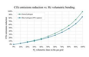
H2 blending concept. Theoretically, H2 blending offers an easily implemented strategy for reducing CO2 emissions from burning natural gas. The existing natural gas transportation network is enormous, offering a ready-made means of transporting the cleaner burning fuel gas blend to existing users.
Ideally, existing natural gas combustion equipment (industrial boilers, heaters, gas-fired home appliances, etc.) could burn the cleaner-burning H2 mix, reducing CO2 emissions on a global scale. GHG emission reductions are tied directly to the concentration of H2 in the mix, so as clean sources of H2 become available, they could be used to increase the H2 blend to as high as possible.
While this concept sounds promising, there are stark realities associated with H2 blending that limit its implementation well below the theoretical maximums.
H2 blending realities. The first challenge associated with H2 blending is caused by H2 itself. High concentrations of H2 can defuse into the walls of metal pipelines, making them prone to cracking and stress corrosion. The rate of H2 embrittlement depends on many factors, including the specific metals involved, the level of existing corrosion and stress in the pipe, the concentration of H2 and the operating pipeline pressures.
The existing natural gas transportation network is vast and aging, so its ability to handle high concentrations of H2 is difficult to predict. Overall, the long-term potential risk of pipeline failure appears to increase with increasing concentrations of H2, but lower concentrations of H2 seem to have little effect on the pipeline infrastructure.
Another challenge for H2 blending stems from the differences in energy and physical density of H2 vs. CH4. H2 combustion creates less energy than CH4 (FIG. 2). In addition, the specific gravity of H2 (2) is substantially less than that of CH4 (16), so the resulting fuel gas blend has a lower density. Combining these two factors reduces the energy delivery capacity of a pipeline for a given operating pressure, and that reduction increases with H2 concentration.
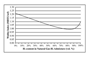
If the pipeline infrastructure can handle higher pressures, raising the operating pressure and delivering the same net energy is possible, but this increases compression costs. One option to address these issues is injecting H2 closer to the point of use. This limits pipeline exposure and compression issues, but each injection station will have associated CAPEX and OPEX, increasing the blending net cost considerably.
There are other challenges associated with H2 blending. Higher concentrations of H2 affect flame formation and stability, and H2 concentrations higher than 30% have a different electrical classification, raising equipment costs.
For all these reasons, lower blended concentrations of H2 are a much more viable option in the immediate future. The potential CO2 emission reduction of the resulting blend is less dramatic, but the numerous challenges associated with high H2 concentrations are largely eliminated. Several global pilot studies suggest a H2 blend of 20%–25% can be safely implemented within the existing natural gas distribution network, while performing well with existing combustion equipment.
Blended H2 metering. Extensive studies have investigated the flow measurement of natural gas/H2 blends. Coriolis meters are often the best solution for mass flow metering, and they can handle the full range of H2 blends from 0%–100% concentration (FIG. 3). Coriolis meters are usually limited in size (16” or less) but alternative solutions are available for larger line sizes.
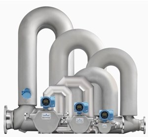
As mentioned, Coriolis meters are not usually used for larger bore pipe natural gas metering due to line size limitations, but they are an excellent choice for the smaller, pure H2 flowmeter injections required in most H2 blending applications.
Differential pressure transmitters are another option for natural gas pipelines, but the measurements must be compensated for component density, as well as temperature and pressure effects, and the pressure drop created by the orifice plate results in additional operating costs due to line loss.
Therefore, most natural gas metering applications use multipath ultrasonic flowmeters (FIG. 4). These meters cost less than Coriolis meters in larger line sizes, have virtually no pressure drop and are available in line sizes up to 42”.
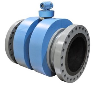
Multipath technology improves flow measurement accuracy and reliability by making multiple measurements across many areas of the pipe to compensate for fluid dynamics and inconsistent flow profiles. Performance testing of these meters under real world conditions suggests these meters can measure blends of H2 up to 25%, with minimal loss in accuracy.
Blended H2 controls. A typical H2 blending station is shown in FIG. 5 and includes a full-bore ultrasonic flowmeter to measure the incoming gas flow, a Coriolis meter and control valve to measure and control the H2 addition, and a downstream gas chromatograph to confirm the resulting blend.
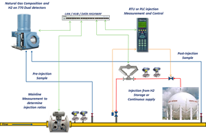
Both flowmeters should be pressure and temperature compensated for maximum accuracy, and an industrial chromatograph should be used to measure incoming and exit gas quality to confirm the resulting blended gas meets specifications.
Blended H2 case studies. Several countries and organizations have implemented pilot studies to better understand the pros, cons, limitations and benefits of H2 blending in real-life applications. The UK implemented a HyDeploy trial at Keele University to blend H2 gas into the local natural gas grid to supply residential halls, student facilities and offices. The project proved that 20% H2 could be blended with natural gas in the existing natural gas infrastructure, with virtually no modification to the transportation infrastructure or the fuel-burning equipment.
The U.S. Department of Energy (DOE) started the HyBlend initiative to study the feasibility of H2 blending in the U.S. This multi-faceted project is investigating the impact of H2 blending on existing pipeline materials of construction and the optimization of H2 production and fuel cell facilities, and it is creating lifecycle emission models for various alternate fuel pathways. That project is ongoing, but early results look promising.
Takeaways. Using the existing natural gas transmission infrastructure, H2 blending with natural gas can yield significant and immediate GHG reductions. While higher H2 blend concentrations may be feasible for specific applications, 20%–25% blends can be implemented with existing transportation pipelines and fuel-burning equipment, with little to no modification.
Existing multipath ultrasonic meters can handle this level of blending with minimal impact on accuracy, and research is ongoing to create modified meters to handle a much broader range of H2 blending. Coriolis flowmeters can be used for pure H2 flow measurement in H2 blending applications. Industrialized gas chromatographs are well suited to measure incoming and outgoing gas streams to confirm product quality, and to adjust the ratio controls as necessary to keep the blend on specification.
Based on the available research, it is likely that H2 blending will be employed as clean H2 sources become available and price competitive. If specified correctly, existing instrumentation and controls are available for these applications, and ongoing research may yield improved options.
NOTES
a Emerson’s Rosemount™ 3418 meter
About the author

MARTIN SCHLEBACH is a senior business development director and flow consultant for Emerson. He has more than 35 yr of measurement experience, focused mainly on ultrasonics. Schlebach is an active and contributing member of several industry committees, including AGA TMC, PRCI MTC and API COPM. He earned a degree in electronic engineering from SAIT Polytechnic in Calgary, Alberta.

