News
Online Feature: Control valve selection for H2 electrolyzer applications
V. VASKOVA and SERGIO ZAGHEN, Emerson, St. Louis, Missouri
The global demand for renewable energy has spurred a multitude of large-scale solar and wind projects, but one major drawback of these sources of energy is intermittency because power generation is dependent on daylight hours and wind patterns. As these sources become a larger portion of the global power supply, effective energy storage solutions will play a crucial part in providing reliable, consistent electricity.
Battery technology is advancing but faces limitations regarding capacity and cost. An alternative solution can be found in electrolyzers, where excess energy is used to create green hydrogen (H2), which can be stored, transported and eventually used by the process industry. This avoids the undesired carbon dioxide (CO2) emissions associated with the combustion of hydrocarbon fluids.
H2 electrolyzers are being produced and implemented at scale but this type of equipment creates challenges for the control valves in this process. This article discusses how H2 electrolyzers work, and it highlights considerations for selecting the right control valves for this application.
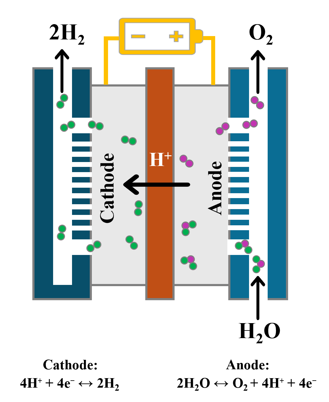
Electrolysis and electrolyzer technology. Electrolysis is a fundamentally simple process that uses electricity to separate water into H2 and oxygen. The major components of an electrolyzer include the electrolysis cell—which consists of a cathode, an anode and a semi-permeable membrane—and some type of electrolyte. Direct current (DC) drives the cell and generates oxygen on the anode and H2 on the cathode (FIG. 1). In a typical electrolyzer, multiple cells are combined to create a stack.
The electrolysis process is reversable, so excess energy can be utilized to create green H2 when renewable sources are generating too much power, and that stored H2 can be used to produce large quantities of green energy when renewable generating capacity is inadequate.
Today, there are four major types of electrolyzer technologies in use (FIG. 2). All use the same fundamental electrolysis process, but each accomplishes the reaction using different process conditions, and different materials for the membranes and electrodes.
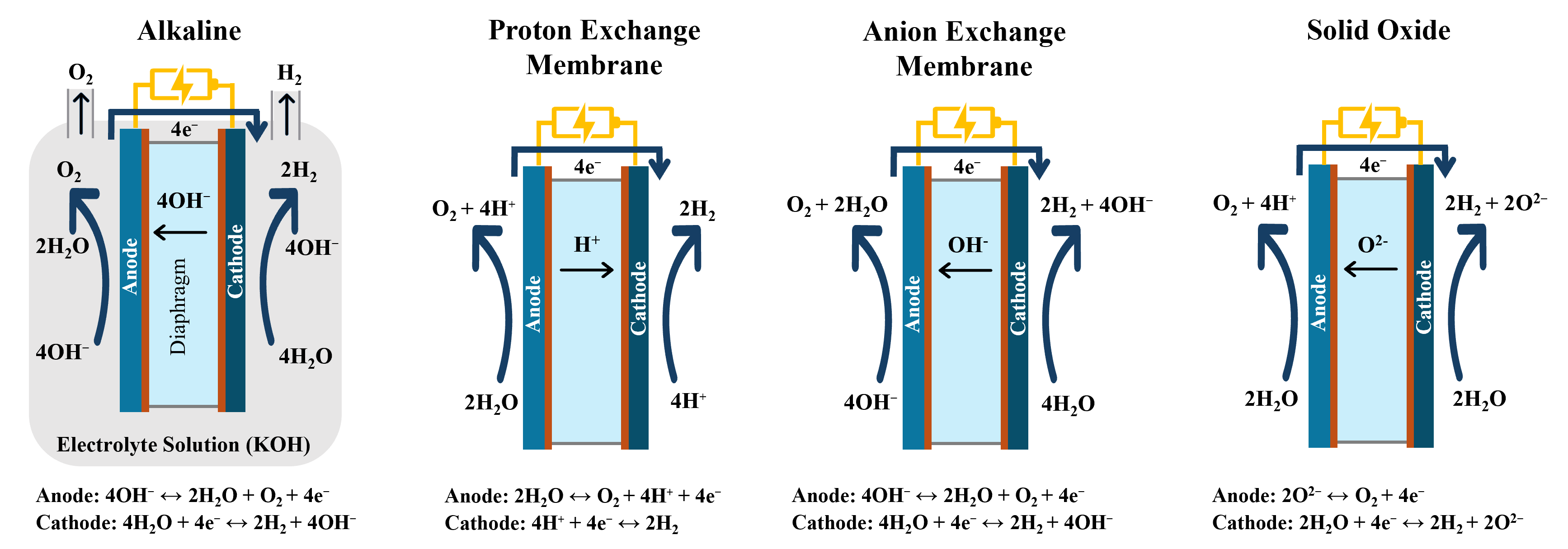
Alkaline electrolyzers are a cost competitive, mature technology and make up two-thirds of the global electrolyzer capacity. They dominate the chlorine and fluorine industries and operate around 60°C–80°C (140°F–176°F) and up to 30 bar (420 pounds per square inch). Unfortunately, alkaline electrolyzers are less efficient than other electrolyzer technologies.
A solid oxide electrolyzer (SOEC) uses heat and steam to drive the process and significantly improve efficiency. They operate at lower pressures but require elevated temperatures, around 500°C–850°C (930°F–1,560°F), so they are best applied in industrial applications where excess heat is available, such as ammonia production. SOEC is a relatively new technology, with only a few demonstration projects underway.
Anion exchange membrane (AEM) is a new electrolysis technology and has become the preferred solution for small scale electrolyzers. Its efficiency matches proton exchange membrane (PEM) electrolysis, but it operates at lower pressures and uses less expensive electrode materials. It remains largely uncommercialized at this time but holds promise based on initial testing.
PEM electrolyzers are being deployed at scale globally and will be the focus of this article. The process runs at relatively low temperatures and pressures of 50°C–80°C (122°F–176°F) and 70 bar (1,000 psi), is relatively simple and boasts high efficiency. The process does require exotic metallurgy for the electrodes, so initial capital cost can be high, but this technology has three major advantages.
First, it allows for faster startups and quicker turndowns, which increases flexibility. Second, it delivers H2 at high pressure, so there is no need to have an expensive compression system downstream. Third, it is modular, so scalability is easier.
PEM process. With the PEM process, ultrapure water (UPW) is pumped into the anode side of the electrolyzer stack. The stack is the heart of the electrolyzer, and it is where the process of splitting water molecules takes place. DC power strips water molecules in the anode, producing oxygen, free electrons and H2 ions. H2 ions pass through a semipermeable perfluorinated acid ionomer membrane, where they pick up the electrons from the DC power to form H2 molecules.
As H2 leaves the stack, it passes through the cathode separator to remove water, which is returned to the process for reuse. Green, pressurized H2 leaves the separator and is sent for final usage, but only after the treatment required to reach the desired purity via dehydration and deoxygenation is achieved.
The key control valves for this process are also shown in FIG. 3, and in general can be grouped into three major categories: UPW control, H2 and oxygen valves. In addition to these main groups, there are also valves for utilities. Each group of valve applications has specific challenges that must be addressed.
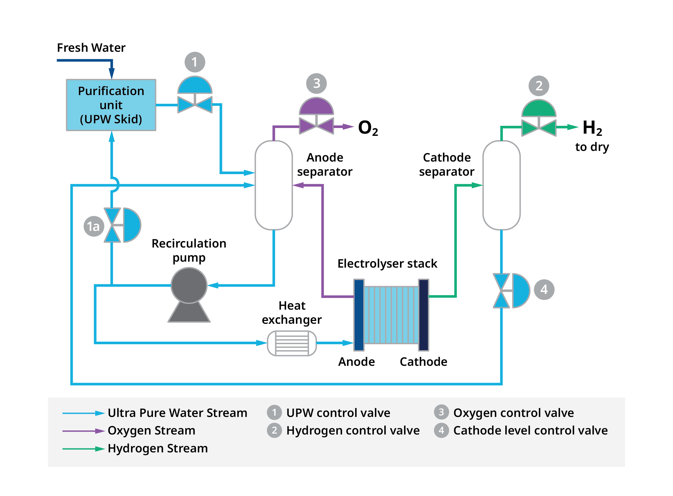
UPW valves. This group of valves includes the valve that regulates the flow of UPW to the process (Valve 1 in FIG. 3), as well as the optional control valve that recirculates the UPW back to the water purification unit (Valve 1a in FIG. 3).
Acceptable electrolyzer stack performance requires a high level of purity in the feed water, so UPW is used instead of freshwater or demineralized water. Impurities must be avoided to prevent contamination of the expensive electrodes in the stack. However, UPW can dissolve metals or impurities under certain conditions, so material selection is important to avoid any release of ions into the UPW. Typically, all wetted parts should be cleaned to avoid any chance of contamination and then machined to a very smooth finish. Stainless steel 316 material typically provides the best tradeoff between cost and performance.
These valves must regulate highly variable flows and pressure drops during start-up, shutdown and operation, so a wide control range is necessary. Globe valve designs offer a good solution for these applications, with trim options available to cover the typical process conditions, from startup to full load.
H2 control valves. The H2 control valves maintain backpressure on the cathode separator (Valve 2 in FIG. 3). During startup, the pressure drop across the valve will be very high, but once in production, the valve should maintain minimal pressure drop to increase efficiency (FIG. 4).
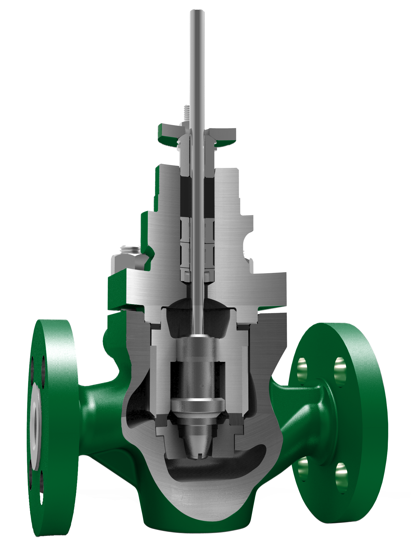
The controllability for the H2 valves is more critical compared to the UPW valves because of the higher differential pressure across the valve. During startup or until reaching the required level of H2 purity, the fluid flowing through the valve can reach full pressure drop.
Globe valves are still the best solution, but the final configuration will depend on many factors, including flowrates and operating procedures. One optimal configuration would be a three-valve design with one valve for venting/startup, and two valves operating in split range to handle the produced H2 flow. The final configuration should avoid over engineering the valve (e.g., complex characterized cages) in favor of more standard solutions that are more cost effective, compact and easier to maintain, with shorter lead times—even if it means using two or three valves.
Control valves design is critical because H2 can diffuse into some metals and cause embrittlement. To address this issue, valve manufacturers should base their design following engineering best practices according to the National Association of Corrosion Engineers (NACE) MR1075/ISO 15156. Standards for H2 piping systems, such as the American Society of Mechanical Engineers (ASME) B31.12 or the European Industrial Gases Association (EIGA) DOC 121, can also be referenced. However, field experience, lab testing and references in other industries will provide the best guidance for material and design selection.
Packing fugitive emissions are another potential hazard for these valves. H2 is very flammable and has a low ignition point, and H2 leaks are easily ignited and burn with an invisible flame. Low-emission packing is therefore a must, but the packing must be well designed to allow free valve movement for tight control, even as leakage is kept to the low parts per million level.
Fugitive emissions also apply to the flange connections between the valve and the pipeline. Weld connections are virtually zero leakage, but they increase installation cost and make maintenance more difficult when removal of a valve is necessary. Traditional raised face flanges or grooved flanges [British Standard Pipe Parallel (BSPP) standard, tongue and groove] are acceptable solutions to address this issue.
Oxygen valve. The oxygen valve (Valve 3 in FIG. 3) bleeds oxygen off the anode separator and maintains proper backpressure on that vessel.
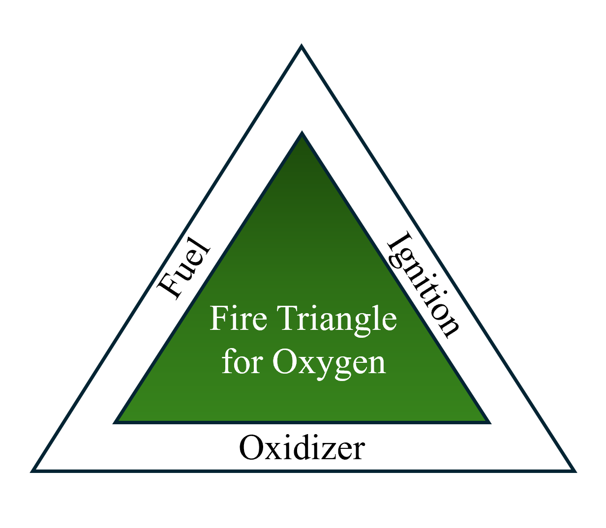
Pure or almost pure oxygen flows need special attention. Oxygen at high concentration works as an oxidizer, with the valve itself as a potential fuel. To prevent a fire hazard, this valve should be designed following the best practices guidelines [i.e., Compressed Gas Association (CGA) G-4.14 or the EICA Doc 13 publication on oxygen piping systems can be referenced for design guidelines]. Oxygen-compatible materials, both metal and non-metal, should be used, and they should be tested if needed per the Federal Institute for Materials Research guidelines.
In addition, any valve in oxygen service must undergo rigorous cleaning procedures to avoid the slightest oil or contamination. If it is not properly cleaned and sealed during shipment, the valve can explode or catch fire when placed into service (FIG. 5).
In most cases, this valve is also taking a full pressure drop when oxygen is vented to atmosphere, so proper sizing and a low noise trim will usually be required for this application.
Cathode level control valve. The cathode level control valve is part of the UPW valve group, but it requires special attention.
The cathode level control valve (Valve 4 in FIG. 3) controls the water level in the cathode separator and returns that water back to the process for reuse. Despite the low solubility of H2 in water, the stack outlet pressure and temperature allow part of the H2 to dissolve into the water.
The challenges are similar to the ones found with the UPW valve, but this application adds the difficulty of handling H2 outgas as the liquid moves through the valve due to the pressure drop of 30 bar or more. This valve requires the proper materials of construction to avoid water contamination, and it must also be designed to handle the erosion risk created by H2 released downstream of the valve.
Final valve selection. The best valve body style can vary based on the specific operating parameters of the electrolyzer in question and the size of the facility. Before sizing and selection, the reader is encouraged to obtain a full understanding of the startup, shutdown and normal operating conditions of the stack. Due to the pressures involved, there can be significantly different pressure drops depending on operating mode.
It is also wise to understand how steady or variable the incoming power will be because quickly varying power can create large process dynamics that must be handled by the valves in question. Fast and accurate valve positioning will likely be required to handle this type of operation, and other variations typical of the PEM process.
There are many control valve options and alternatives, so if a reader has questions or concerns, they should seek an automation partner with expertise in the industry, preferably one that has provided valves proven in this application. While the technology is moving quickly, there are many successful installations already in production, so it is wise to leverage that knowledge whenever possible.
About the authors

VERA VASKOVA is the sales development manager for Emerson flow controls products in the sustainable industries segment. In this role, she works with global customers to help them build a strategy to meet their net-zero commitments, and to reduce emissions and energy consumption by implementing the best available technologies. Vaskova has more than 10 yr of experience in the control valve market, focusing on business planning and strategy. She earned an MS of science degree in economics from Plekhanov Russian University of Economics in Moscow.

SERGIO ZAGHEN is the industry director for flow controls in Europe at Emerson, where he spearheads the development of the control valve market for H2 original equipment manufacturers (OEMs). In this role, he collaborates closely with the engineering departments of multiple OEMs to identify optimal technical and economic solutions, enabling these companies to enhance their competitiveness and scale efficiently. Zaghen earned an MS degree in chemical engineering from the Politecnico di Milano University, and an MBA from the IE Business School in Madrid.
From The Archives
Connect with H2Tech
